Weft Thread Tension during Filling Insertion Process on Projectile Weaving Machines
Tensión de hilo de trama durante el proceso de inserción de llenado en máquinas de tejer
Weft Thread Tension during Filling Insertion Process on Projectile Weaving Machines
Científica, vol. 20, no. 2, pp. 83-91, 2016
Instituto Politécnico Nacional
Received: 01/12/2015
Accepted: 14/06/2016
Abstract: Weft thread tension during filling insertion process on projectile weaving machines is time dependent and is characterised by big values of tension force maximums. As one can see from a number of investigations a weft yarn moves by jerks and vibrates though a projectile inserting a weft moves with almost constant velocity after its starting. In accordance with observations a weft thread forms slacks along it in the course its filling insertion. It follows owing to a short time during which a weft comes to a movement, a quick compensator lever movement and elastic properties of a yarn. When a weft slack is hauled in, a weft undergoes a jerk and so a maximum of a weft thread tension arises. First weft slack arises when a compensator lever quickly sinks and releases a weft thread. Then a projectile comes to a movement and hauls a weft slack. A part of a weft between a weft accumulator and a compensator comes to its movement during a short time and thus extremely big maximum of a weft thread tension force arises. We deduce formulas for this maximum of tension force, which we use as a basis for resolving of a problem of compensator function optimisation with the aim of to reduce a weft thread tension. Results of theoretical consideration and weft thread tension measurements are reported below.
Keywords: projectile weaving machine, weft tension, slack, compensator lever movement, jerk.
Resumen: La tensión del hilo de trama durante la fase de inserción se caracteriza por altos valores máximos de la fuerza de tensión. Como se puede ver, a partir de una serie de estudios, el hilo de trama se mueve con tirones y vibra, mientras que el proyectil acelera sin sacudidas y se mueve con velocidad prácticamente constante después de la aceleración. De acuerdo con las observaciones, el hilo de trama forma holguras a lo largo de ella. Esto ocurre debido al corto periodo de tiempo durante el cual la trama se pone en marcha, el movimiento rápido de la palanca de compensador y propiedades elásticas del hilo de trama. Cuando se selecciona una holgura del hilo, el hilo de trama sufre un tirón y así surge la tensión máxima del hilo de trama. La primera holgura se produce cuando la palanca del compensador desciende (antes de inicio del movimiento de proyectil) y suelta el hilo de trama. Entonces el proyectil en movimiento recoge la holgura. Parte de la trama, entre almacenador de trama y el compensador, se pone en marcha por un corto tiempo, y por lo tanto, se produce grande fuerza extrema de tensión del hilo de trama. Derivamos una fórmula para esta fuerza de tracción máxima, que utilizamos como base para solución del problema de la optimización del funcionamiento de compensador para reducir esta tensión máxima del hilo de trama. Los resultados de análisis teórico y la medición de la tensión del hilo de trama se presentan a continuación.
Palabras clave: máquina de tejer con proyectiles, la tensión de la trama, holgura, palanca de retroceso (compensador), tirón.
Over the past 40 years the Sulzer shuttleless weaving machine has been the undisputed "frontrunner" for all but a few specialist applications. The range of flexibility of the machine has been steadily expanded and there is now little difference between its fabric-producing capabilities and that of the automatic bobbin-change loom [1]. In these weaving machines they use a projectile equipped with a gripper for a weft thread to insert it into a shed. This principle of projectile filling insertion allows the insertion of practically any weft yarn [2]. Projectile filling insertion systems function with high economical efficiency and low energy consumption.
A sketch of a weft tread drawing on projectile weaving machine is shown on Fig.1. Weft thread 2 is taken up directly from fixed bobbin 1 or by means of a weft thread accumulator 3.
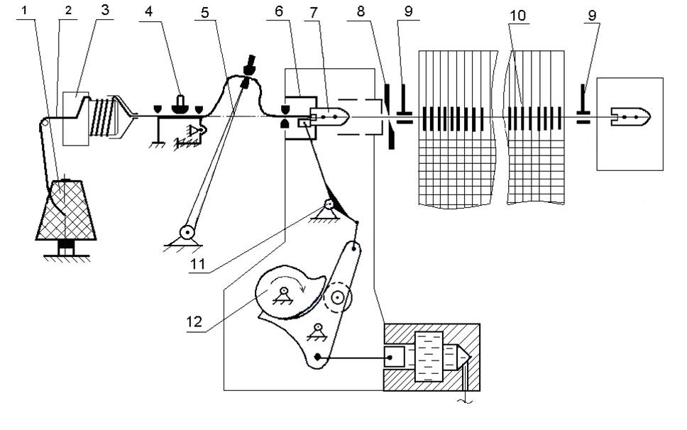
FIG. 1.
Weft thread filling insertion into a shed.
It passes through a brake system 4, a weft thread conductor hole of a compensator lever 5 and is fixed in a gripper of a projectile 7 by pressing force. A projectile is started by a projectile picking mechanism at an instant of its unloading owing to elastic force power of rod shaft 11. A projectile transports a weft thread at a velocity up to 35 m/s and up to 1000 g, where g is acceleration of gravity, through directing channel of a slay 10 into reception box. After braking in reception box a projectile with a weft thread comes back to fabric selvage, releases a weft thread, and is lowered on a conveyer. A weft thread is cut off by means of scissors 8. A weft thread is clamped in thread holders 9 of selvage formers, moves toward a fabric fell and is beaten-up by a reed.
Experimental studies and measuring of a weft thread tension in an area between a compensator and a projectile on projectile weaving machines during its filling insertion have shown that a weft thread movement is jerky [2], [3], [4] and is accompanied by big maximums of a weft thread tension (Fig. 2). There is a danger of technological breakdowns being quickened, such as a break of a weft thread or letting a weft thread to slip out from projectile clamps [5].
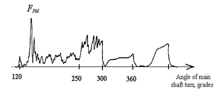
FIG. 2.
Typical diagram of a weft thread tension during filling insertion process on a projectile weaving machine.
A lever of compensator begins to sink before projectile starting. Such way angles of a weft thread rounding of thread conductor hole in a compensator lever and thread conductor holes nearest to compensator lever become smaller to reduce friction and weft tension when a projectile will pull a weft then. Thus two slacks arise from each side of a compensator lever. First maximum of weft thread tension corresponds to the beginning of a projectile starting. In accordance with experimental results this first maximum is not so big as a next second maximum of a weft thread tension.
A projectile continues its movement and hauls a slack from a side nearest to it. After the haul of this slack have finished the haul of a slack between a thread conductor hole of a compensator lever and a thread conductor nearest to a brake system begins. There is no big increase of a weft thread tension at this moment. A projectile quickly moves and pulls a weft thread, so this slack decreases nevertheless a compensator lever sinks down. When a weft thread between a thread conductor of a compensator lever and a thread conductor nearest to a brake system is becoming almost like straight line a remaining part of a weft thread between a thread conductor of a brake system nearest to a compensator and a thread conductor of a weft thread accumulator begins sharply to move. So second maximum of a weft thread tension is arising. In accordance with investigations this maximum of a weft thread tension is the biggest one [3], [4]. Owing to weft elastic properties and inertia forces a weft thread continues to vibrate and forms repeated slacks again some times. So there are a few maximums of a weft thread tension on a tension diagram of a weft thread. These third and next maximums of a weft thread tension are smaller than a second one.
Let us consider a situation when there are no slacks before of a projectile starting and a compensator lever sinks down very quickly and in concord with the acceleration of a projectile to avoid a creation of slacks near a compensator lever and thread conductors nearest to it. As it follows from the dynamic analysis it is practically impossible to carry out without an additional increase of a weft thread tension because of inertia and elastic properties of a weft yarn. From technical point of view it is difficult to fulfil because of it would demand of a very high precision of projecting of a compensator cam. This goal would entail an increase of dimensions of a compensator cam and a compensator roller and distances between the axes of a compensator cam and a compensator lever to avoid a big strain between a cam and roller or a big angle between a normal to contacting parts of cam and roller surfaces and direction of movement of roller axis. From other side it would be difficult to adjust a compensator and projectile picking mechanisms for concordant function.
Further we give a short review of a method of estimation of maximum thread tension force when a thread slack is hauled by a projectile in a case without of a compensator lever [3]. In next sections this method is generalized for weft thread tension estimation for filling insertion process on projectile weaving machines. Results of theoretical and experimental investigation of weft thread tension forces and optimisation of filling insertion process are presented below.
2. Maximum of thread tension force in a simple case of a thread slack hauling
The simplest problem of a thread tension determination
in presence of a slack, which is hauled by a projectile, may be formulated as
it follows. A thread of linear density  is located between points with
coordinates xb and xp and forms a slack between thread conductors with
coordinates 0 and x0 as it is shown on Fig. 3. A projectile moves with constant
velocity Vp and pulls a thread by its end xp with tension force Fp . A part of a
thread between xb and 0 is motionless at initial moment of time. A slack is
hauled by a projectile and a thread between points and becomes almost as a straight line. So a part of a thread between xb and
0 begins sharply to move and therefore a significant maximum of a thread
tension arises in a thread between points 0 and xp .
is located between points with
coordinates xb and xp and forms a slack between thread conductors with
coordinates 0 and x0 as it is shown on Fig. 3. A projectile moves with constant
velocity Vp and pulls a thread by its end xp with tension force Fp . A part of a
thread between xb and 0 is motionless at initial moment of time. A slack is
hauled by a projectile and a thread between points and becomes almost as a straight line. So a part of a thread between xb and
0 begins sharply to move and therefore a significant maximum of a thread
tension arises in a thread between points 0 and xp .
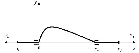
FIG. 3.
Geometry of the simplest case of a slack hauling.
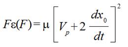
This problem was considered in [3]. In a case when thread extensibility is not important a maximum of a thread tension force in a part of a thread between points x0 and xp is
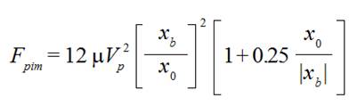 (1)
(1)A tension force Fp is essentially big during characteristic time interval
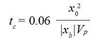 (2)
(2)When a distance  is becoming a big enough that a longitudinal wave of a
thread extension is not able to reach point xb and come back to point 0 during this characteristic
time interval an extensibility of a thread is important. In this case a maximum
of a thread tension force Fpem in a part of a thread between
points x0 and xp is the solution
Fpem with respect to
F of the equation
is becoming a big enough that a longitudinal wave of a
thread extension is not able to reach point xb and come back to point 0 during this characteristic
time interval an extensibility of a thread is important. In this case a maximum
of a thread tension force Fpem in a part of a thread between
points x0 and xp is the solution
Fpem with respect to
F of the equation
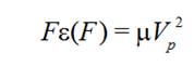 (3)
(3)that is
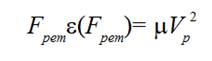 (3a)
(3a)where  is relative
extension of a thread when a tension force F is applied to it.
is relative
extension of a thread when a tension force F is applied to it.
Relative extension of a thread  can be measured for any thread as its tension diagram. Usually
dependence of relative extension
can be measured for any thread as its tension diagram. Usually
dependence of relative extension  from
tension force F is not linear and may be written approximately by the relation
from
tension force F is not linear and may be written approximately by the relation
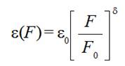 (4)
(4)where  is relative extension of a thread when tension force F0 is applied to
it,
is relative extension of a thread when tension force F0 is applied to
it,  is adjustment parameter.
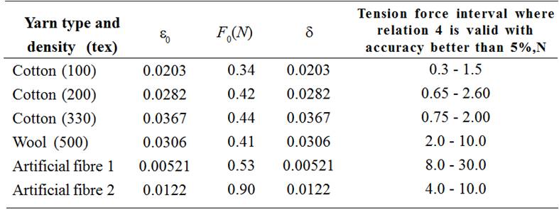
As it was shown in [3] with the aim to determine a maximum value of a thread tension in a part of a thread between points x0 and xpin the simplest case represented on Fig. 3 anyone needs to evaluate maximum tension forces Fpimin accordance with Formula (1) and Fpim in accordance with Equation (3a) and choose the smallest value from Fpim and Fpem . If a value of Fpim appears smaller than a value of Fpem it means that a thread may be considered as inextensible or almost inextensible one. If a value of Fpem appears smaller than a value of Fpimit means that a thread is extensible one during the process (see Table 1).
3. Maximum of weft thread tension force during filling insertion process on projectile weaving machine
3.1. Theory
On Fig. 4 it is shown geometry corresponding to filling insertion process on a projectile weaving machine.
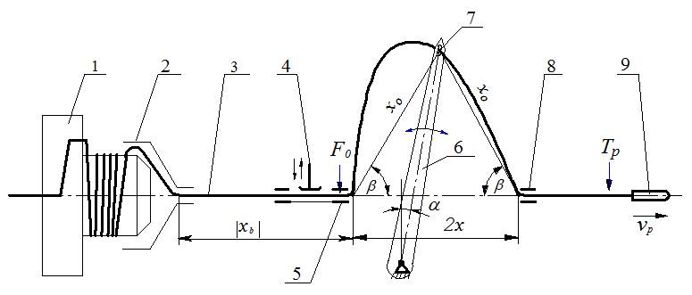
FIG. 4.
Geometry of a weft thread slack hauling on a projectile weaving machine.
In previous simple consideration we neglected by friction forces because of rounding angles near thread conductors were small at final stage of a thread hauling. Now we need to take into account friction forces in thread conductors and the influence of a compensator lever movement.
After a slack hauling between thread conductors 5 and 7 (Fig. 4) is finished a remaining part of a weft thread between a weft thread accumulator and a thread conductor 5 begins sharply to move and reaches velocity value,
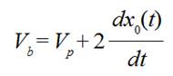 (5)
(5)where Vp is a projectile velocity, x0( t ) is decreasing distance between thread
conductors 5 and 7 (or 7 and 8) owing to a compensator lever sinking down.
Derivative  is negative and must
be taken at the moment of time when a weft thread between points 5 and 7 is
becoming a straight line.
is negative and must
be taken at the moment of time when a weft thread between points 5 and 7 is
becoming a straight line.
Taking into account a rounding angle  near
a thread conductor 5 and a friction force in this thread conductor with
coefficient of friction kf we can write the equation of motion for a part of a
weft thread between a weft thread accumulator and a thread conductor 5
near
a thread conductor 5 and a friction force in this thread conductor with
coefficient of friction kf we can write the equation of motion for a part of a
weft thread between a weft thread accumulator and a thread conductor 5
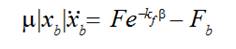 (6)
(6)where F is a weft thread tension force near a thread conductor 5 from a side of a slack arch, is a weft thread tension force created by a weft thread accumulator. The equation (6) holds now instead of Equation (10) of [3].
Making mathematical treatment almost analogously to [3] and having in mind Equation (6) we receive for a maximum of a weft thread tension force directly near a thread conductor 5 from a side of an accumulator the expression
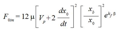 (7)
(7)We neglected in it an influence of a weft accumulator tension force Fb as a small one if to compare with right side of the expression (7).
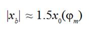
Taking into account that rounding angles in sum equal  when a weft thread passes through thread conductors 5, 7, 8 we can derive for a maximum of weft thread tension force in a weft thread part between a thread conductor 8 and a projectile the formula
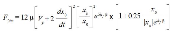 (8)
(8) where values of  and
and  must be taken at the moment of time when a weft thread between points 5 and 7 is becoming a straight line.
The formulas (7) and (8) are valid in a case when a weft thread extensibility is not important.
A weft thread tension force Fp is essentially big during characteristic time interval
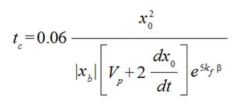 (9)
(9)When a distance  is becoming a big enough that a longitudinal wave of a
weft thread extension is not able to reach point xb and come back
to point 0 during this characteristic time interval an extensibility of a
thread is important analogously to a simple case of a slack hauling considered
above. In this case maximum of a weft thread tension force F0em directly near a
thread conductor 5 from a side of a weft thread accumulator is the solution
with respect to F of the equation
is becoming a big enough that a longitudinal wave of a
weft thread extension is not able to reach point xb and come back
to point 0 during this characteristic time interval an extensibility of a
thread is important analogously to a simple case of a slack hauling considered
above. In this case maximum of a weft thread tension force F0em directly near a
thread conductor 5 from a side of a weft thread accumulator is the solution
with respect to F of the equation
 (10)
(10)that is
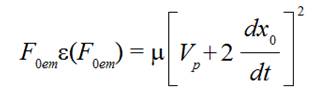 (10a)
(10a)where  is relative extension of a weft thread when a tension
force F is applied to it.
is relative extension of a weft thread when a tension
force F is applied to it.
To determine a maximum of a weft thread
tension force in a part of a weft thread between nearest to projectile thread
conductor 8 and a projectile we need to take into account rounding angles in
sum equal  when a weft thread passes
through thread conductors 5, 7, 8 in accordance with Fig. 4. Thus we receive
for a maximum of a thread tension force in a weft thread part between a thread
conductor 8 and a projectile the formula for case of extensible weft thread
when a weft thread passes
through thread conductors 5, 7, 8 in accordance with Fig. 4. Thus we receive
for a maximum of a thread tension force in a weft thread part between a thread
conductor 8 and a projectile the formula for case of extensible weft thread
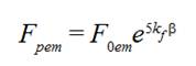 (11)
(11)Analogously to simple case of a thread slack hauling considered above with the aim to determine a maximum value of a weft thread tension force in a part of a weft thread between a nearest to a projectile thread conductor 8 and a projectile in the case of projectile weaving machine with moving compensator lever represented on Fig. 4 anyone needs to evaluate maximum tension forces Fpim in accordance with formula (8) and Fpem in accordance with Equation (10a) and formula (11) and choose the smallest value from Fpim and Fpem . If a value of Fpim ppears smaller than a value of Fpemit means that a weft thread may be considered as inextensible or almost inextensible one. If a value of Fpem appears smaller than a value of Fpim it means that a weft thread is extensible one during the process.
4. Graphic methods for determination of functions being involved into formulas
To determine the moment of time when a weft thread
between points 5 and 7 is becoming a straight line during filling insertion
process and appropriate values of functions in formulas (8), (11) or Equation (10a) at this moment it is advisable to plot graphs of a weft thread length
released by a compensator lever  velocity
of this length releasing
velocity
of this length releasing 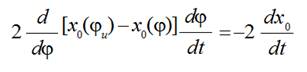 distance that a projectile passed from the beginning its
starting
distance that a projectile passed from the beginning its
starting

Friction function for a weft thread tension increasing at the expense of rounding angles  (Fig. 5), where
  is angle of the main shaft turning of projectile weaving machine,
  value of this angle when a compensator lever is staying in upper position and a lever and projectile are still motionless,
  is angular velocity of the main shaft rotation.
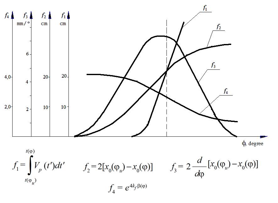
FIG. 5.
Graphs of functions for maximum weft thread calculations.
Function  can be
determined for definite projectile weaving machine by turning of the main shaft
by hand and measuring a weft thread releasing on condition that a brake system
does not allow a weft thread to pass through a thread conductor 5, (Fig. 4).
Function
can be
determined for definite projectile weaving machine by turning of the main shaft
by hand and measuring a weft thread releasing on condition that a brake system
does not allow a weft thread to pass through a thread conductor 5, (Fig. 4).
Function  can be obtained by
differentiation of function
can be obtained by
differentiation of function  relative to angle
  and multiplication on
  as it was written early. Distance

can be found by a high-speed filming of a projectile movement from the first moment of its starting. Friction function can be obtained by measuring of a tension force of a weft thread that has to be applied by its end to drag a weft thread through thread conductors 5, 7, 8 (Fig. 4), when to a weft thread end nearest to a weft thread accumulator a definite tension force is applied. A value of  is just a ratio of drag tension force to definite force applied at fixed angle of the main shaft turning
  .
.
At the moment of time when a weft thread between points 5 and 7 is becoming a straight line after a slack hauling is finished, Fig. 4, distance that a projectile passed from the beginning its starting equals to weft thread length released by a compensator lever
 (12)
(12) So this moment corresponds to the point of intersection of graphs of functions  and
and  on Fig. 5.
It determines the values of functions  and
and  at the moment of time when the biggest maximum of weft thread tension force takes place and corresponding angle of the main shaft turning
  . Vertical line passing through the point of intersection shows on the values of other functions
  and
and  at this moment of time. The values of
  or
or  can be obtained as
  or
or  .
.
5. Comparison experimental and theoretical results
For the verification of derived equations
and formulas the second maximums of a weft thread tension were measured during
filling insertion process on projectile weaving machine STB2.216 at usual
tuning of it with rotation velocity of the main shaft 220 revolutions per
minute and velocity of projectile Vp = 20 m/s. Distance between thread conductors 5 and 8
equaled 2 x = 0.14 m, lever
length L = 0.195 m. In accordance
with the exploitation instructions angle between lever of compensator and
vertical line, when a compensator lever was staying in upper position and lever
and projectile were still motionless,  9 degrees. As it was mentioned above a first maximum of a thread tension
corresponds to the beginning of a projectile starting and relatively is not big
in comparison with next ones. In accordance with the investigations [3], [4]
the second maximums of a weft thread tension are the biggest ones.
9 degrees. As it was mentioned above a first maximum of a thread tension
corresponds to the beginning of a projectile starting and relatively is not big
in comparison with next ones. In accordance with the investigations [3], [4]
the second maximums of a weft thread tension are the biggest ones.
Experiments were carried out with cotton
weft threads of different linear densities 100, 210, and 330 tex. The
measurements were fulfilled with two values of  , which equaled to 0.235 m
and 0.302 m. Three changeable cams of compensator were used in the course of
measurements. These cams had almost the same profiles corresponding to interval
of angles of main shaft turning j where compensator lever released a weft thread. The profiles were
characterized by different beginning of lever sinking relatively to beginning
of projectile starting. First cam ensured the beginning of lever sinking
approximately on 35 degrees earlier the beginning of projectile starting,
second one on 15 degrees, and third one on 3 degrees. That way the values of
angle
, which equaled to 0.235 m
and 0.302 m. Three changeable cams of compensator were used in the course of
measurements. These cams had almost the same profiles corresponding to interval
of angles of main shaft turning j where compensator lever released a weft thread. The profiles were
characterized by different beginning of lever sinking relatively to beginning
of projectile starting. First cam ensured the beginning of lever sinking
approximately on 35 degrees earlier the beginning of projectile starting,
second one on 15 degrees, and third one on 3 degrees. That way the values of
angle  (Fig. 4), and friction
function values were different for that or other cam at the moment of time when
a weft thread between points 5 and 7 was becoming a straight line after a slack
hauling was finished.
(Fig. 4), and friction
function values were different for that or other cam at the moment of time when
a weft thread between points 5 and 7 was becoming a straight line after a slack
hauling was finished.
The results of experiments and calculations of the biggest (second) maximums of weft thread tension forces and standard deviations for a part of weft threads between thread conductor 8 and projectile are presented in Table 2.
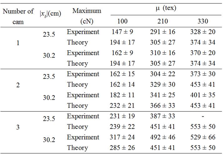
As it follows from the viewing of Table 2
the experimental and theoretical data are in good agreement. The biggest
maximums of weft thread tension forces are increasing with increase of distance  between weft thread accumulator and nearest to brake system thread
conductor of compensator and with increase of weft thread linear density. First
cam of compensator that ensured the beginning of lever sinking approximately on
35 degrees earlier the beginning of projectile starting had appeared the best
one in the sense, that the biggest maximums of weft thread tension forces were
smaller for this cam than when other two cams were used.
between weft thread accumulator and nearest to brake system thread
conductor of compensator and with increase of weft thread linear density. First
cam of compensator that ensured the beginning of lever sinking approximately on
35 degrees earlier the beginning of projectile starting had appeared the best
one in the sense, that the biggest maximums of weft thread tension forces were
smaller for this cam than when other two cams were used.
6. Optimisation of filling insertion process
6.1. Theoretical analysis
From the results of analysis and calculations fulfilled with the aim to decrease the biggest maximum of a weft thread tension forces based on equations and formulas stated above it follows that exists optimum angle  corresponding to the moment when a slack hauling between thread conductors 5 and 7 (Fig. 4) is finished and a weft thread between these conductors is becoming a straight line during filling insertion process. Optimum angle
  depends from geometrical parameters of a compensator such as its length L and distance 2 x between thread conductors 5 and 8. Angle
  depends also from a projectile velocity Vp , derivative
  and angular velocity of the main shaft rotation
  .
.
Influences of friction coefficient kf and adjustment parameter  for approximation of relative extension of a thread
  by formula (4) are not so big if
friction coefficient kflies in interval from 0.20 to 0.25 and
adjustment parameter
by formula (4) are not so big if
friction coefficient kflies in interval from 0.20 to 0.25 and
adjustment parameter  lies in interval
from 0.34 to 0.90.
lies in interval
from 0.34 to 0.90.
The biggest maximum of a weft thread
tension force decreases with decreasing of distance  between weft thread accumulator and nearest to a brake system thread
conductor of a compensator. Influence of smaller distances
between weft thread accumulator and nearest to a brake system thread
conductor of a compensator. Influence of smaller distances  becomes
essential when
becomes
essential when
 (13)
(13)Where  is the distance x0 between thread
conductors 5 and 7 when a weft thread between these conductors is becoming a
straight line and the biggest weft thread maximum takes place,
is the distance x0 between thread
conductors 5 and 7 when a weft thread between these conductors is becoming a
straight line and the biggest weft thread maximum takes place,  is corresponding angle of the main
shaft turning.
is corresponding angle of the main
shaft turning.
For the projectile weaving machine
STB2.216 with rotation velocity of the main shaft 220 revolutions per minute
and velocity of projectile Vp = 20 m/s, distance between thread conductors 5 and 8
equalled 2 x = 0.14 m and former
lever length Lf= 0.195 m
it was founded that new lever length Ln = 0.207 m could
be established after small reconstruction of compensator mechanism. In this
case for the cams with the typical value of derivative  and cotton weft threads tested optimum angle
  equaled 65 degrees. To suit this optimum angle
  new angle
  was established between lever of compensator and vertical
line, when compensator lever was staying in upper position and a lever and
projectile were still motionless, instead former value
was established between lever of compensator and vertical
line, when compensator lever was staying in upper position and a lever and
projectile were still motionless, instead former value  .
.
The brake system was reconstructed with the aim to short it size along weft thread passing through it. It allowed to obtain the smallest distance  between weft thread accumulator and thread conductor 5 of compensator nearest to brake system.
The calculations with new values of Ln = 0.207 m,  and
and  values were laying in interval from 0.06 m to 0.302 m were fulfilled for first cam that ensured the beginning of lever sinking approximately on 35 degrees earlier the beginning of projectile starting. It was predicted an essential decrease of biggest maximums of weft thread tension forces from 1.7 to 2.0 times.
7. Comparison of results on weft thread tension measuring at usual tuning of projectile weaving machine and after optimisation of filling insertion process
Experiments were carried out with cotton
weft threads of linear densities 210 and 330 tex during filling insertion
process on projectile weaving machine STB2.216 with rotation velocity of the
main shaft 220 revolutions per minute and velocity of projectile Vp = 20 m/s. Distance between thread conductors 5 and 8 equaled 2 x = 0.14 m. First cam of compensator
was installed that ensured the beginning of a lever sinking approximately on 35
degrees earlier of the beginning of a projectile starting. Tension forces of
weft threads were measured with lever length Lf = 0.195 m and angle  established between lever of compensator and vertical line,
when compensator lever was staying in upper position and lever and projectile
were still motionless, with two values of distance
established between lever of compensator and vertical line,
when compensator lever was staying in upper position and lever and projectile
were still motionless, with two values of distance  equaled 0.302 m and 0.235 m. Measurements of weft thread
tension forces were fulfilled also after the reconstructions of compensator
mechanism and brake system with lever length Ln = 0.207 m
and angle
equaled 0.302 m and 0.235 m. Measurements of weft thread
tension forces were fulfilled also after the reconstructions of compensator
mechanism and brake system with lever length Ln = 0.207 m
and angle  established with
three values of distance
established with
three values of distance  equaled
0.302 m, 0.235 m and 0.060 m. Three types of maximums of weft thread tension
forces were measured: first maximums Fpm1 that arose
after beginning of projectile starting, second maximums Fpm2 after first
slack hauling between thread conductors 5 and 7 (Fig. 4) was finished, third
maximums Fpm3 after second (repeated) slack hauling between
thread conductors 5 and 7 was finished. Mean values of weft thread tension
forces Fpmean were measured during the time interval from
the beginning of projectile starting and just till brake system was put in
action at the end of projectile flight. All weft thread tension force
measurements were fulfilled on weft thread part nearest to thread conductor 8
from the side of projectile. The results of measuring are presented in Tables 3
and 4.
equaled
0.302 m, 0.235 m and 0.060 m. Three types of maximums of weft thread tension
forces were measured: first maximums Fpm1 that arose
after beginning of projectile starting, second maximums Fpm2 after first
slack hauling between thread conductors 5 and 7 (Fig. 4) was finished, third
maximums Fpm3 after second (repeated) slack hauling between
thread conductors 5 and 7 was finished. Mean values of weft thread tension
forces Fpmean were measured during the time interval from
the beginning of projectile starting and just till brake system was put in
action at the end of projectile flight. All weft thread tension force
measurements were fulfilled on weft thread part nearest to thread conductor 8
from the side of projectile. The results of measuring are presented in Tables 3
and 4.
It follows from the viewing of Tables 3
and 4 that there was appreciable reduce of maximums of weft thread tension
forces Fpm1 , Fpm2 , Fpm3and mean values
of weft thread tension forces Fpmean measured during
the time interval from the beginning of projectile starting and just till brake
system was put in action at the end of projectile flight after the
reconstructions of compensator mechanism and brake system with new lever
length Ln = 0.207 m and
angle  established. In that way the theory that was presented
above allowed to find optimum parameters of compensator mechanism with the aim
to decrease the biggest weft thread tension force maximums. Fortunately it
appeared that these optimum parameters entailed also the decrease of other
maximums of weft thread tension forces and mean thread tension forces.
established. In that way the theory that was presented
above allowed to find optimum parameters of compensator mechanism with the aim
to decrease the biggest weft thread tension force maximums. Fortunately it
appeared that these optimum parameters entailed also the decrease of other
maximums of weft thread tension forces and mean thread tension forces.
8. Conclusions
Weft thread tension during filling insertion process on projectile weaving machines was investigated theoretically and experimentally with the aim to decrease weft thread tension and in that way to favour reliability of the process. It was shown that weft thread moves by jerks owing to slack formation and subsequent hauling by a projectile. When a weft thread between thread conductors is becoming a straight line after a slack hauling is finished a maximum of weft thread tension force is observed. Equations and formulas for determination the biggest maximum of a weft thread tension force were developed. Obtained theoretical and experimental data are in good agreement. The search of optimal parameters for filling insertion process based on stated equations and formulas and suitable reconstruction of compensator mechanism and brake system ensured essential decrease of maximum values and mean value of weft thread tension forces for weft thread being investigated.
References
[1] A. Ormerod and W. Sondhelm, Weaving: Technology and Operations, Manchester, England: Textile Institute, 1995.
[2] S. Adanur, Handbook of Weaving, Alabama, USA: CRC Press, 2001.
[3] L. Oleinikova and V. Oleinikov, "Motion of thread with a jerk: Theory and experiment," The Journal of the Textile Institute, vol. 96, no. 6, 381-388, 2005.
[4] J. Lünenschloß and S. Schlichter,"Die Fadenbelastung in Kette und Schuß in Abhängigkeit von der Schußeintrags-frequenz und anderen Webmaschinenparametern," Melliand Textilberichte, vol. 61, no. 2, pp. 93-98, 1987.
[5] A. D. Bogza and V. A. Ornatskaya, Investigation of Reliability of Process of Lining of Weft String on Weaver's Machine Tools, Moscow: Legkaya Industriya, 1978.