Engenharia Elétrica
Pulse Mask Controlled HFAC Resonant Converter for high efficiency Industrial Induction Heating with less harmonic distortion
Conversores ressonantes de corrente alternada de alta frequência controlados por máscara de pulso para aquecimento indutivo industrial de alta eficiência com baixa distorção harmônica
Pulse Mask Controlled HFAC Resonant Converter for high efficiency Industrial Induction Heating with less harmonic distortion
Acta Scientiarum. Technology, vol. 38, no. 2, pp. 173-183, 2016
Universidade Estadual de Maringá
Received: 20 September 2014
Accepted: 06 October 2015
Abstract: This paper discusses about the fixed frequency pulse mask control based high frequency AC conversion circuit for industrial induction heating applications. Conventionally, for induction heating load, the output power control is achieved using the pulse with modulation based converters. The conventional converters do not guarantee the zero voltage switching condition required for the minimization of the switching losses. In this paper, pulse mask control scheme for the power control of induction heating load is proposed. This power control strategy allows the inverter to operate closer to the resonant frequency, to obtain zero voltage switching condition. The proposed high frequency AC power conversion circuit has lesser total harmonic distortion in the supply side. Modeling of the IH load, design of conversion circuit and principle of the control scheme and its implementation using low cost PIC controller are briefly discussed. Simulation results obtained using the Matlab environment are presented to illustrate the effectiveness of the pulse mask scheme. The obtained results indicate the reduction in losses, improvement in the output power and lesser harmonic distortion in the supply side by the proposed converter. The hardware results are in good agreement with the simulation results.
Keywords: series resonant inverter, zero voltage switching, energy efficiency, pulse width modulation, THD, power control.
Resumo: Este artigo discute o controle de pulso por máscara em frequência fixa baseado no circuito de conversão CA (Corrente Alternada) de alta frequência para aplicações de aquecimento indutivo industrial. Convencionalmente, para carga de aquecimento por indução, o controle de potência de saída é conseguido, usando os conversores de modulação com base de largura de pulso. Os conversores convencionais não garantem a condição de voltagem zero para a minimização de perdas de comutação. Neste trabalho, propõe-se um esquema de controle de máscara de pulso para o controle de potência da carga de aquecimento por indução. Esta estratégia de controle de energia permite que o inversor opere mais perto da frequência de ressonância, para obter a condição voltagem zero de comutação. O circuito proposto de conversão de energia em alta frequência CA tem menor distorção harmônica total no lado da entrada. A modelagem da carga IH, o desenho de circuito de conversão e o princípio do regime de controle e sua implementação usando controlador PIC de baixo custo são brevemente discutidos. Os resultados da simulação obtidos usando o ambiente Matlab são apresentados para ilustrar a eficácia do regime de máscara de pulso. Esses resultados indicam a redução de perdas, melhoria do poder de saída e menor distorção harmônica no lado da entrada pelo conversor proposto. Os resultados de hardware estão em boa concordância com os resultados de simulação.
Palavras-chave: comutação de tensão zero, eficiência energética, modulação de largura de pulso, THD, controle de potência, inversor de série ressonante.
Introduction
nduction heating (IH) is a non-contact heating process. It uses the high frequency electricity to heat materials that are electrically conductive. Since it is non-contact, the heating process does not contaminate the material being heated. It is also very
efficient compared to the other heating methods, since the heat is actually generated inside the workpiece (Acero et al., 2008; Lucia, Acero, Carretero, & Burdio, 2013). This can be contrasted with the other heating methods where heat is generated with a flame or heating element, which is then applied to the workpiece. Clean and fast heat supplied to the workpiece meets the increased requirements with regard to environmental protection (Ahmed & Nakaoka, 2006; Acero et al., 2008). In IH process, the surroundings are not exposed to any thermal and atmospheric pollution. The advantage of this process is producing the heat inside the work piece without the need for any external heat source. For these reasons, induction heating lends itself to some unique applications in industry. Induction heating has been successfully applied to domestic applications due to the advantages of high heating, safety and efficiency (Byun, Choi, Roh, & Hahn, 2000; Meng, Cheng, & Chen, 2011).
High frequency IH system requires specially designed power converters. A large number of inverter topologies have been developed for different applications with the power levels ranging from hundreds of watts to several megawatts for the domestic and industrial applications (Lucia, Burdio, Barragán, Acero, & Carretero, 2011). There is voltage and current fed high frequency AC (HFAC) inverters to transfer high power to the load. Different inverter topologies such as half bridge, full bridge, and single switch have been proposed for IH applications (Lucia, Burdio, Millan, Acero & Barragán, 2010; Park, Lee, & Hyun, 2007; Booma & Ramareddy, 2013). The choice of topology is mainly based on the cost and performance for specific application.
High quality heating depends on the control of power supplied to the load. On the other hand, the main desired feature of the IH power supply is the cost and efficiency. Half bridge series resonant inverter (SRI) fed by voltage source represents the cost effective solution; however, power control has to be done through the control of variable DC voltage. A bridge rectifier with DC link capacitor has been used conventionally for the variation in DC voltage (Saha, Kurl, Ahmed, Omori, & Nakaoka, 2008). This had problems in size; cost and quality of the supply current. Utility current will have more harmonic distortion. Different power control and regulation strategies have been proposed such as pulse width modulation (PWM), pulse frequency modulation and phase shift control. These power control schemes may cause high magnitude of switching losses, because it is not always possible to turn on or off the switching devices at zero voltage or zero current instants (Lucia, Burdio, Millan, Acero, & Puyal, 2009; Carretero, Lucia, Acero, & Burdio, 2011; Pham, Fujita, Ozaki, & Uchida, 2011). Power control by variable frequency operation (Sarnago, Lucia, Mediano & Burdio, 2013a) has several disadvantages including high electromagnetic interference, poor utilization of the components and complex filtering of output voltage ripple. Fixed frequency control techniques (Sarnago Sarnago, Lucia, Mediano & Burdio, 2013b; Lucia et al., 2013) can overcome the above problems.
The aim of the paper is to propose a fixed frequency pulse mask control technique for HFAC converter for IH system to improve the output power with less harmonic distortion. In this paper, a HFAC converter for IH system with single-phase diode rectifier, a single-phase half bridge inverter with MOSFET as power switches and series IH load is described.
The voltage fed half bridge SRI is considered, since it is the most used topology due to its simplicity and less cost. Induction coil and the workpiece is modeled as series connection of inductor (Leq) and resistor (Req), based on its analogy with respect to the transformer. Power control is done using the pulse mask scheme.
In the pulse mask scheme, the inverter operation is maintained at resonance, so that the losses are decreased. In conventional methods, with the increased output power, switching losses are increased. Under pulse mask scheme, switching losses are lower and fixed; the total output power of the inverter is increased. This improves the efficiency of the IH generators for wide power variation. It also overcomes the drawbacks of the conventional control modes. Generally, HFAC converters inject harmonics into the utility (Lucia, Carretero, Palacios, Valeau, & Burdío, 2011). The diode bridge rectifier with the input side T filter is considered in this work. It causes lesser harmonic distortion. With the proposed circuit and control scheme, an improvement in output power and lesser total harmonic distortion (THD) at high frequency working conditions can be achieved. The proposed control technique achieves the linear variation in output power, which makes the control algorithm simpler.
Description of HFAC converter and IH system
Figure 1 shows the main block diagram of HFAC power conversion circuit for IH load. The HFAC conversion circuit diagram using half bridge SRI is shown in Figure 2. The single-phase AC supply is given to the uncontrolled rectifier circuit. T filter is used between AC supply and rectifier to reduce THD.
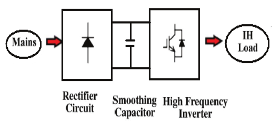
Figure 1
Block diagram of IH power supply circuit.
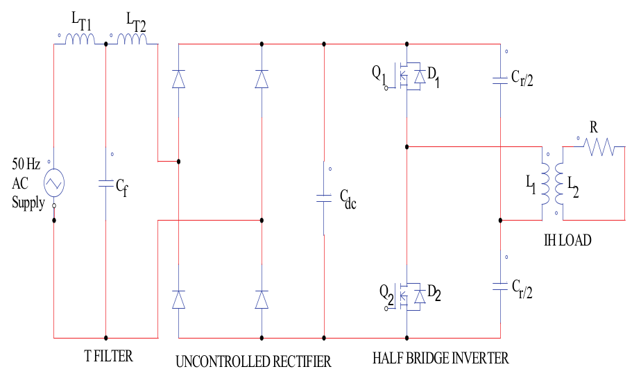
Figure 2
Power circuit diagram.
The T filter consists of two inductors LT1 and LT2 and the capacitor (Cf). The rectifier converts AC supply into DC. After the rectifier, DC link capacitor (Cdc) is connected in parallel, to filter out the ripple contents available in the DC supply. Then DC is given to the half bridge SRI which consists of two MOSFET switches Q1, Q2, two anti-parallel diodes D1, D2 and two resonant capacitors (Cr/2) to produce HFAC supply. IH load connected with the inverter receives the supply from the inverter.
Modeling of IH load
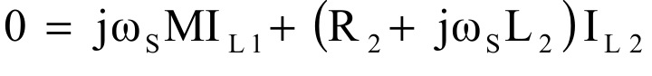
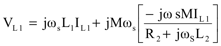
IH load consists of a work coil and workpiece as shown in Figure 3(a). Basically, IH load is a transformer representation of the electromagnetic induction action between the work coil (primary) and the load (secondary). It is difficult to measure the transformer parameters. Therefore, it is better to represent the IH load using a simplified series ReqLeq model. The transformer representation of the load model is shown in Figure 3(b). Where L1 is the inductance of the work coil, L2 is the inductance of the work piece, M is the mutual inductance between the primary and the secondary and R2 is the resistance of the work piece. The equivalent circuit of the load is shown in Figure 4. The equivalent values of the IH system Req and Leq are changed by the geometry, load materials, temperature and excitation frequency. These parameter variations make the output power control harder (Lucía et al., 2011). For this reason, a complete analysis for the equivalent parameters of the IH system is provided here. Loop 1 and 2 in Figure 3(b) yield the following voltage equations 1 and 2.
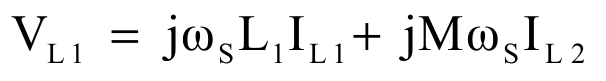 [1]
[1]
 [2]
[2]
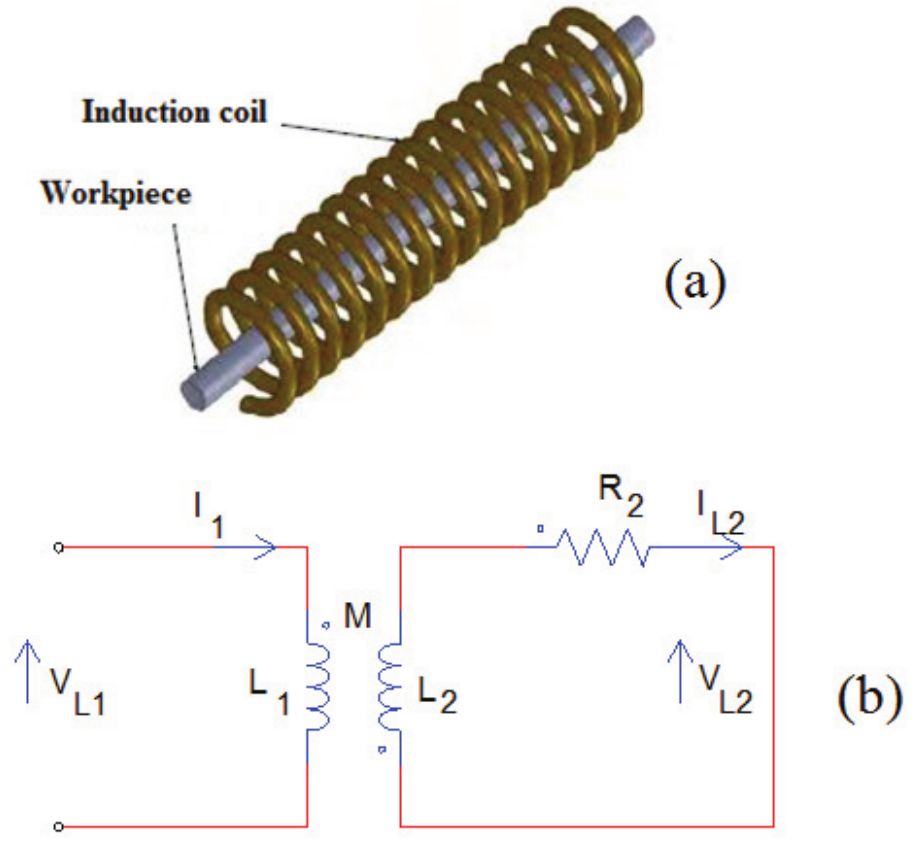
Figure 3
(a) IH load arrangement (b) Transformer equivalent circuit of the IH load.
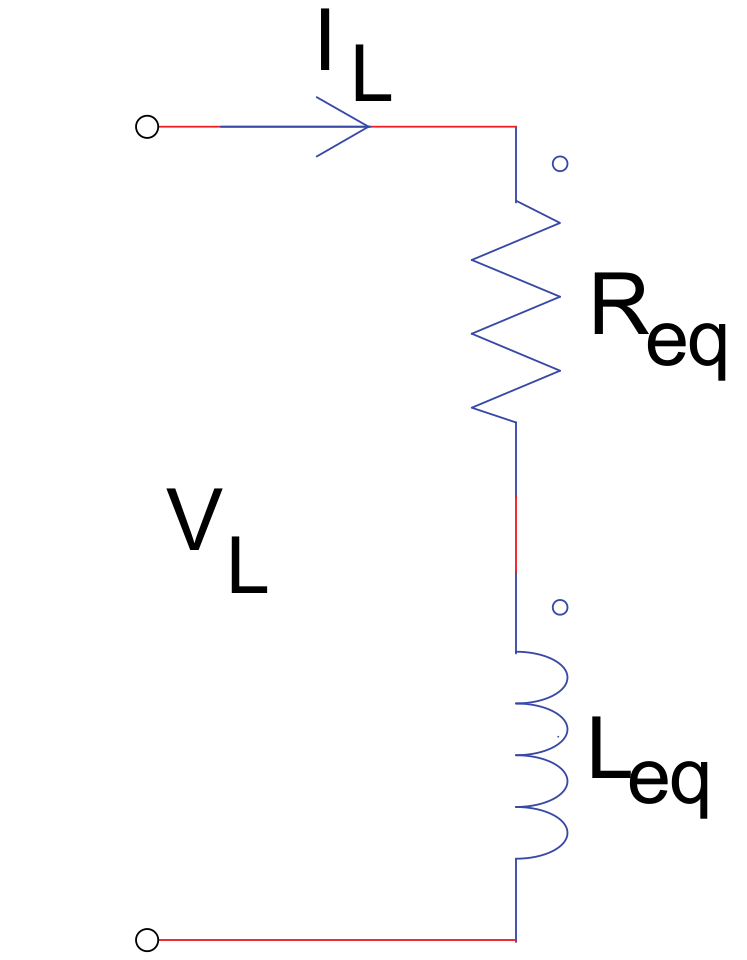
Figure 4
Equivalent circuit of the IH load.
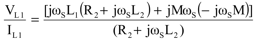
The load current IL2 is obtained from Equation 2 as follows:
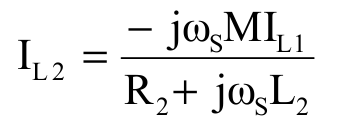 [3]
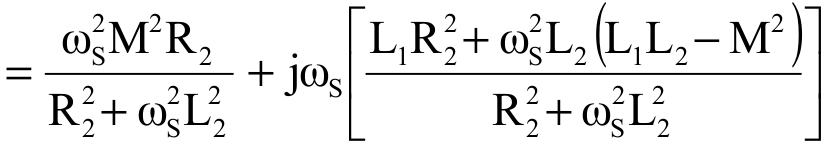
[3]The equations 1 and 3 give the following equations 4, 5, 6, 7, 8 and 9:
 [4]
[4]
 [5]
[5]
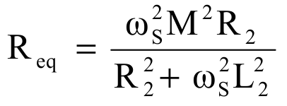
 [6]
[6]
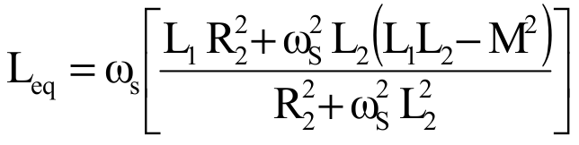
 [7]
[7]
 [8]
[8]
 [9]
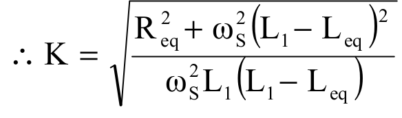
[9]The mutual coupling co-efficient (K) and the time constant of the load (τ) is given in equations 10 and 11.
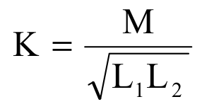 [10]
[10]
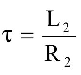 [11]
[11]From equation 9, the following equation 12 is obtained.
 [12]
[12]Solving 9 and 12 yields the following equations 13, 14 and 15.
 [13]
[13]
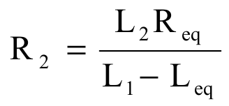
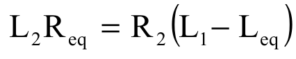 [14]
[14]
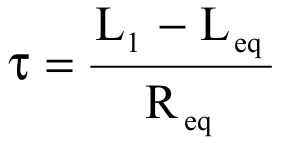 [15]
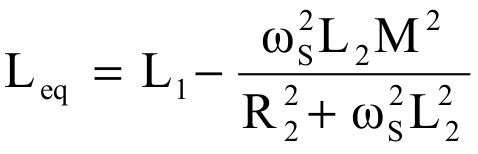
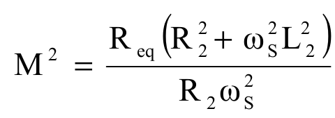
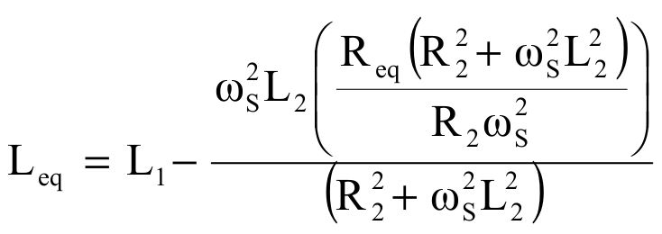
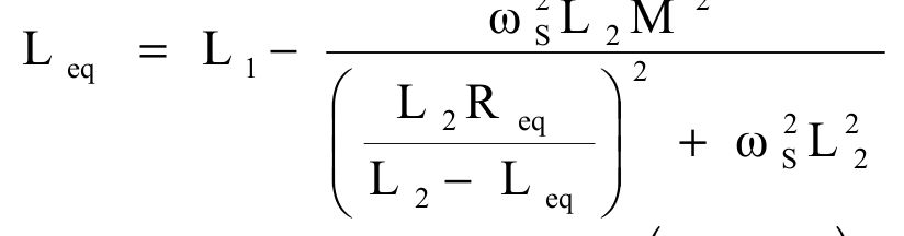
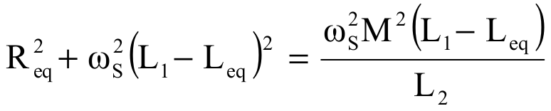
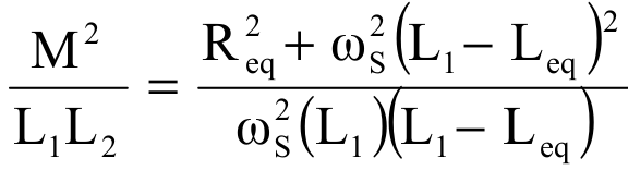
[15]It can be seen from equation 15 that τ can be estimated by using Req, Leq and L1. From equation 14, equation 16 is obtained as:
 [16]
[16]Solving 9 and 16 yields the following equations 17, 18, 19 and 20:
 [17]
[17]
 [18]
[18]
 [19]
[19]
 [20]
[20]where:
; fs is the switching frequency.
The above analysis is used for the design of the circuit parameters. The half bridge SRI is operated at a switching frequency higher than the resonant frequency to achieve ZVS condition. To reduce the switching losses during turn-off, a lossless snubber network (Cs) is added (Lucía et al., 2011; Sarnago, Mediano, & Lucia, 2012). This operation mode ensures zero switching losses.
Design of IH load parameters
The design of IH load parameters for the rated power of 500 W is described in this section. The angular resonant frequency (wr) of the series resonant circuit is given by equation 21:
 [21]
[21]where:
Cr is the resonant capacitance used to obtain the series resonant condition. The normalized angular switching frequency (wn) is expressed as equation 22:
 [22]
[22]The quality factor (QL) of the IH coil is given by equation 23:
 [23]
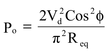
[23]The output power (Po) of the half bridge inverter fed by a DC voltage (Vd) is given by the following equation 24:
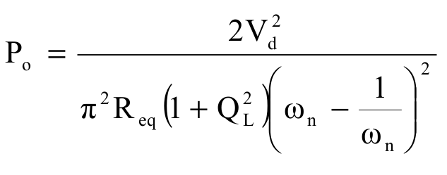 [24]
[24]For the output power Po, the Req of the IH load is given by the equation 25:
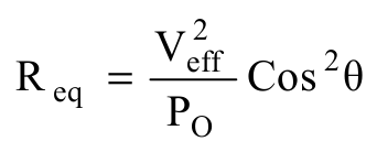 [25]
[25]By using the quality factor (QL) of the resonant circuit, Leq of the heating coil is given by equation 26:
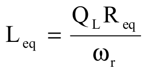 [26]
[26]By the definition of the resonant frequency, the resonant capacitor (Cr) can be calculated using the following equation 27:
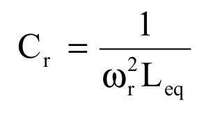 [27]
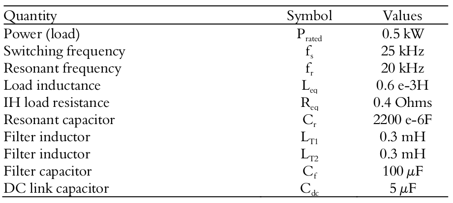
[27]To reduce turn-off losses, a lossless small snubber capacitor (Cs) is used with the inverter switch. Using the above equations, calculations of load parameters are made and they are listed in Table 1.
Pulse mask control strategy
Power control is an important goal to be achieved in an IH load to maintain the required temperature. The heating of the work piece can be controlled by controlling the input power to the working coil of the IH load. Conventionally, this is achieved by the control of the voltage fed SRI using pulse width modulation (PWM) technique. The output power Po of the half bridge voltage fed inverter, given by the equation 24, under resonant condition can be written as equation 28:
 [28]
[28]In the conventional PWM based power control, the output power is controlled through PWM duty cycle (DPWM). DPWM is given by the following equation 29:
 [29]
[29]where:
TON is the turn-on time of the switch and;
T is the total time for one cycle, as shown in Figure 5.
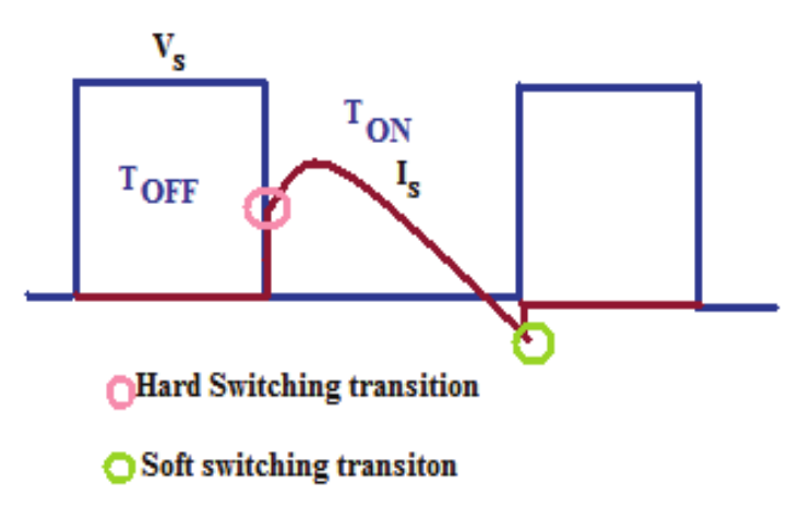
Figure 5
Waveforms for voltage across the switch (Vs) and current through the switch (Is).
The desired output power (Pdesired) can be obtained by variation in DPWM, as given below as equation 30:
 [30]
[30]The DPWM is the control variable for continuous power regulation in PWM method. Hard switching and soft switching transition of the MOSFET switches are shown in Figure 5. During hard switching, both the voltage and current values are not zero, which leads to higher switching losses. However, during the soft switching transition, either the switch voltage or the current becomes zero. In the conventional method, DPWM is varied by varying TON. The variation in TON causes hard switching due to violation in ZVS operation, which leads to higher turn-on/off losses and reduced output power.
To minimize the turn off losses, a pulse mask control is proposed in this paper. In the proposed method, for a control cycle Tc, the inverter transmits power to the load in TM time and it stops working in the remaining (Tc -TM) time as shown in Figure 6. The generation of high frequency pulse masked control pulses are presented in Figure 6. Key waveforms under the proposed scheme are presented in Figure 7. Power is injected into the IH load in TM period due to continuous gate pulses. During the period Tc -TM, zero power is injected into the load due to the masking of pulses. The switches of the SRI are operated above the resonant frequency in order to achieve the ZVS at the turn-off instant. The principle of this scheme is to control the output power Po without changing the turn-on/turn-off instants. Since the switching instants are not changed, the pulse mask scheme offers zero turn-on/off losses. The other advantage of this method is its linear dependency on the output power Po. Gate signals for the switches Q1 and Q2 are presented in Figure 7 (a). Figure 7(b) shows the wave forms for the output voltage (Vo) and output current (Io) in the pulse mask scheme. The output voltage is a discontinous one, while the output current Io is an oscillating one due the high inductance of the IH load. In this paper, the pulse masking modulation index (DM) is considered as control variable. The pulse-masking index DM is given by the following equations 31 and 32:
 [31]
[31]
 [32]
[32]
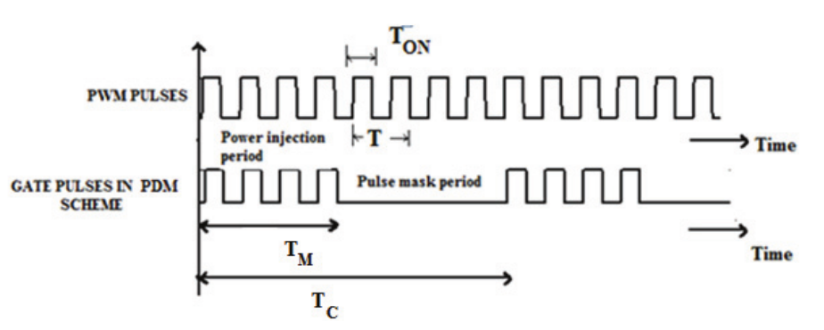
Figure 6
Gate pulses in conventional and proposed scheme.
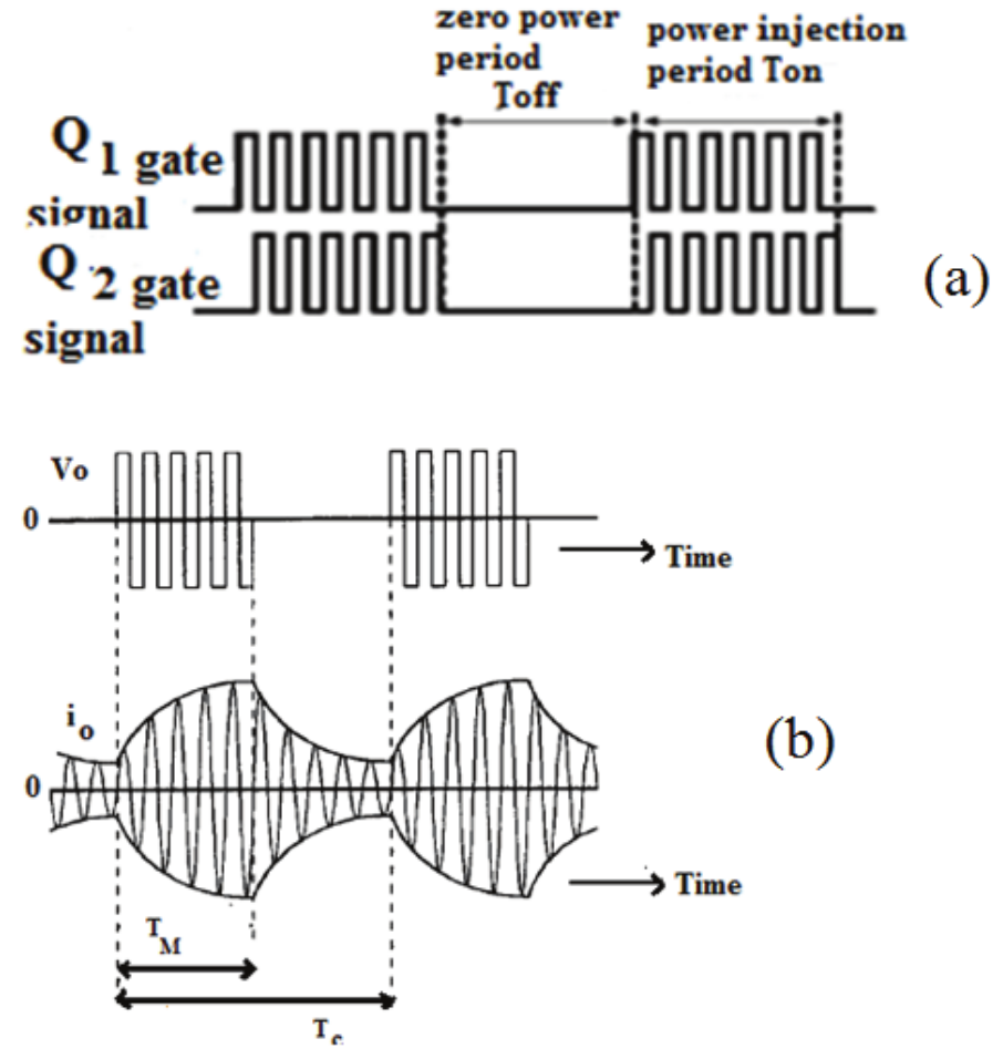
Figure 7
Key waveforms of the proposed scheme (a) Pulses for half bridge SRI switches; (b) Waveforms for output voltage (Vo) and output current (Io).
The desired power is adjusted by controlling the DM. The variation of DM does not change the switching instant of the MOSFET. Consequently, ZVS at turn-off instant is maintained, which reduces in switching losses. For the complete range of load variation, ZVS condition is not disturbed in the pulse mask control scheme. This improves the output power in the proposed scheme compared to the conventional PWM method.
Results and discussions
Schematic of the voltage fed half bridge SRI is developed for time domain simulation using Matlab simulation tool. Simulation of the proposed converter circuit is carried out for an IH load of 0.5 kW operating at the frequency of 25 kHz. The design specifications and the circuit parameters of the proposed HFAC circuit using the commercial MOSFET and diode modules are listed in Table I. The utility side input voltage of 50 Hz frequency is shown in Figure 8 (a). The DC link voltage and the gate pulses for inverter switch Q1 at 50 and 10% DM are shown in Figure 8 (b, c and d), respectively. Pulse masked 25 kHz high frequency gate pulses produced by the proposed scheme are of discontinuous manner. The output voltage (Vo), output current (Io) of the inverter at the pulse masking modulation index of 50 and 10% are shown in Figura 9 a, b, c and d), respectively. Since the waveforms are of high frequency, the expanded view of the Vo and Io are shown in Figure 9 (e and f), respectively. Due to the variation in DM, the average value of voltage Vo and Io varies and causes the variation in the output power. The voltage across the power switch Q1 (Vs1) and current through the switch Q1 (Is1) at the DM of 50 and 10% are shown in Figure 9 (g and h), respectively. These waveforms were obtained using simulation. It can be observed from the waveforms that during current rising and falling instants, the switch voltage is zero. These waveforms prove the soft switching operation of the proposed modulation topology. With both the modulation index DM, ZVS condition is maintained during turning on/off instants.
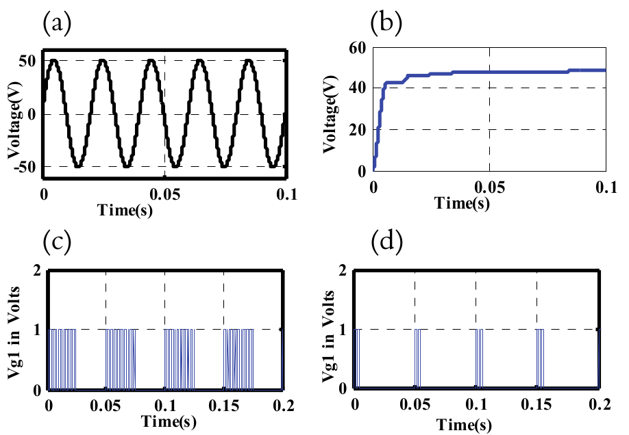
Figure 8
Simulation of output waveforms (a) Utility side input voltage; (b) DC link voltage; (c) Pulse mask scheme gate pulses (Vg1) to switch Q1 at DM of 50%; (d) Pulse mask scheme gate pulses (Vg1) to switch Q1 at DM of 10%.
To validate the pulse mask scheme in SRI, a prototype model rated for 500 W was fabricated. The schematic diagram for the hardware implementation of the power circuit and the control circuit are shown in Figure 10. he power circuit has a diode bridge rectifier, a half bridge SRI and an IH load. Uncontrolled rectifier was constructed using IN5408 diode switches. A half bridge SRI using four power switches was employed for DC-HFAC conversion. MOSFET of IRF840 switches are used since they can withstand maximum voltage of 500 V and current of 8 A. A copper coil of 8 mm thickness was used to build the work coil with an outer diameter of 110 mm. An iron piece of 100-80-45 mm size has been chosen as workpiece.
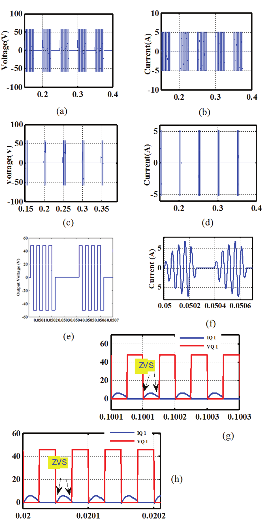
Figure 9
Simulation of output waveforms (a) Output voltage (Vo) at DM of 50%; (b) Output current (Io) at DM of 50%; (c) Output voltage (Vo) at DM of 10%; (d) Output current (Io) at DM of 10%; (e) Zoomed view of output voltage (Vo) at DM of 10%; (f) Zoomed view of output current (Io) at DM of 10%; (g) Voltage across the switch (VQ1) and current through the switch (IQ1) at 50% DM; (h) Voltage across the switch (VQ1) and current through the switch (IQ1) at 10% DM.
The control circuit has PIC16F877A embedded controller, IR2110 driver and (+5V) - (+12V) power supply circuit. Pulse mask control pulses were produced with the embedded controller PIC16F877A. The layout of the hardware prototype is shown in Figure 11 (a). With 100% DM, the output 25 kHz frequency signal and the 50 Hz AC signal are presented in Figure 11 (b).
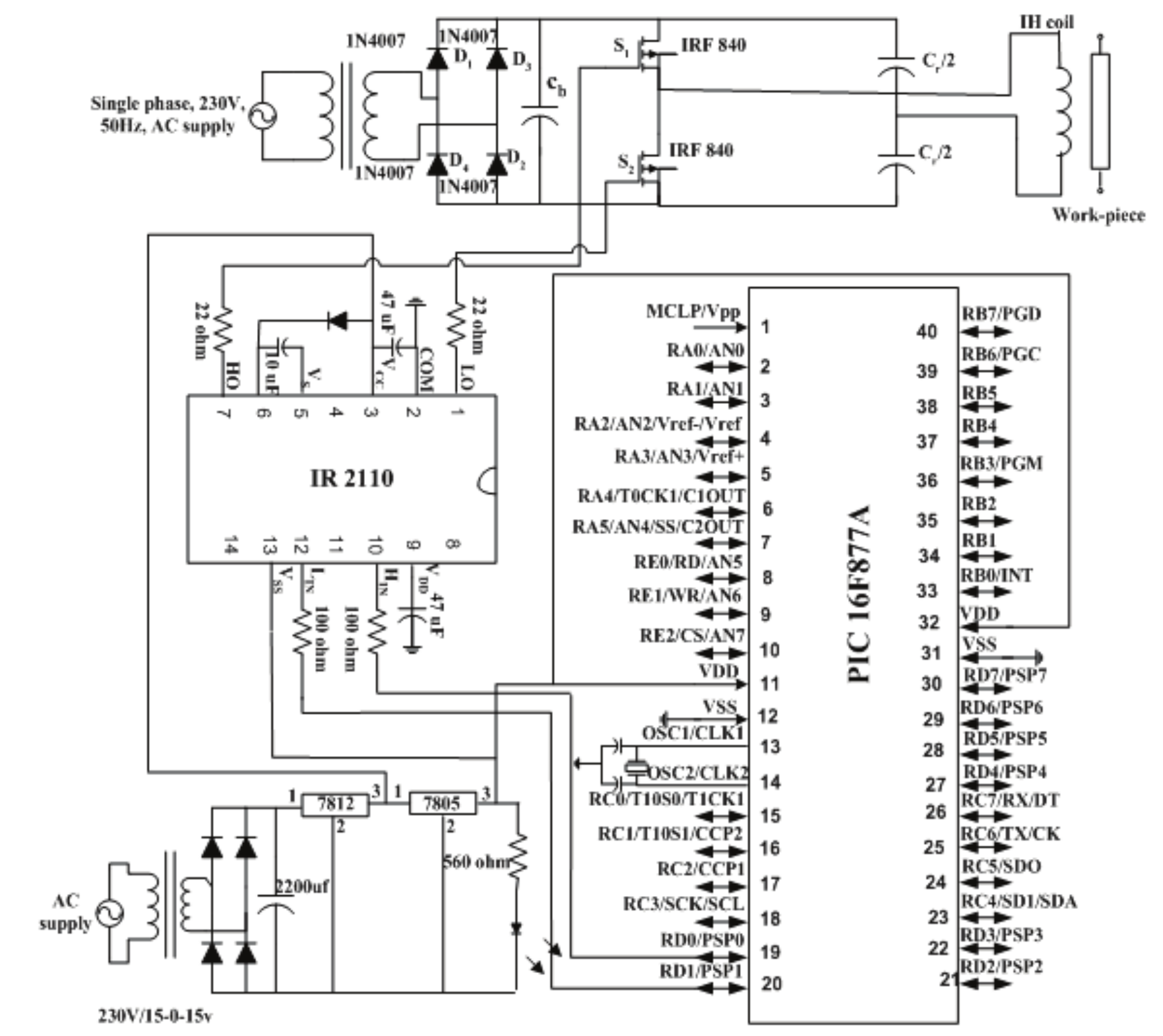
Figure 10
Schematic diagram for the hardware implementation of the HFAC conversion circuit.
The switching pulses for Q1 and Q2 were produced using microcontroller. For the amplification of the output pulses from the micro controller, IR2110 driver circuit was used. The amplified pulses from the driver are applied to the switches, and they are presented in Figure 11 (c). Vo and Io corresponding to DM of 10% are shown in Figure 11 (d) and Figure 12 (a), respectively. The output voltage is of discontinuous manner with the peak amplitude of 47 V and frequency of 25 kHz. The output current was of oscillating nature due to the inductive nature of the load. The peak amplitude of the oscillation was 5.4A with 25 kHz frequency. These experimental results closely agree with the theoretical and simulation results. The voltage across the power switch Q1 (VQ1) and current through the switch Q1 (IQ1) is presented in Figure 12 (b).
It can be observed from the waveforms that during the turning off transition the switch voltage and current are nearly zero. These waveforms indicate the soft switching operation of the proposed modulation topology. Due to the soft switching operation, the total losses that take place in the inverter switches were reduced, as shown in Figure 13 (a). Total losses were calculated with the difference between input and output power. In the proposed scheme, the switching losses were decreased due to ZVS condition. This leads to increased output power in the pulse mask scheme. The output power variation with the variation in the input power in the conventional and the proposed methods is shown in Figure 13 (b). For the same input power, the output power obtained in the proposed scheme is higher. The proposed control scheme can be easily implemented using the low cost PIC16F877A controller.
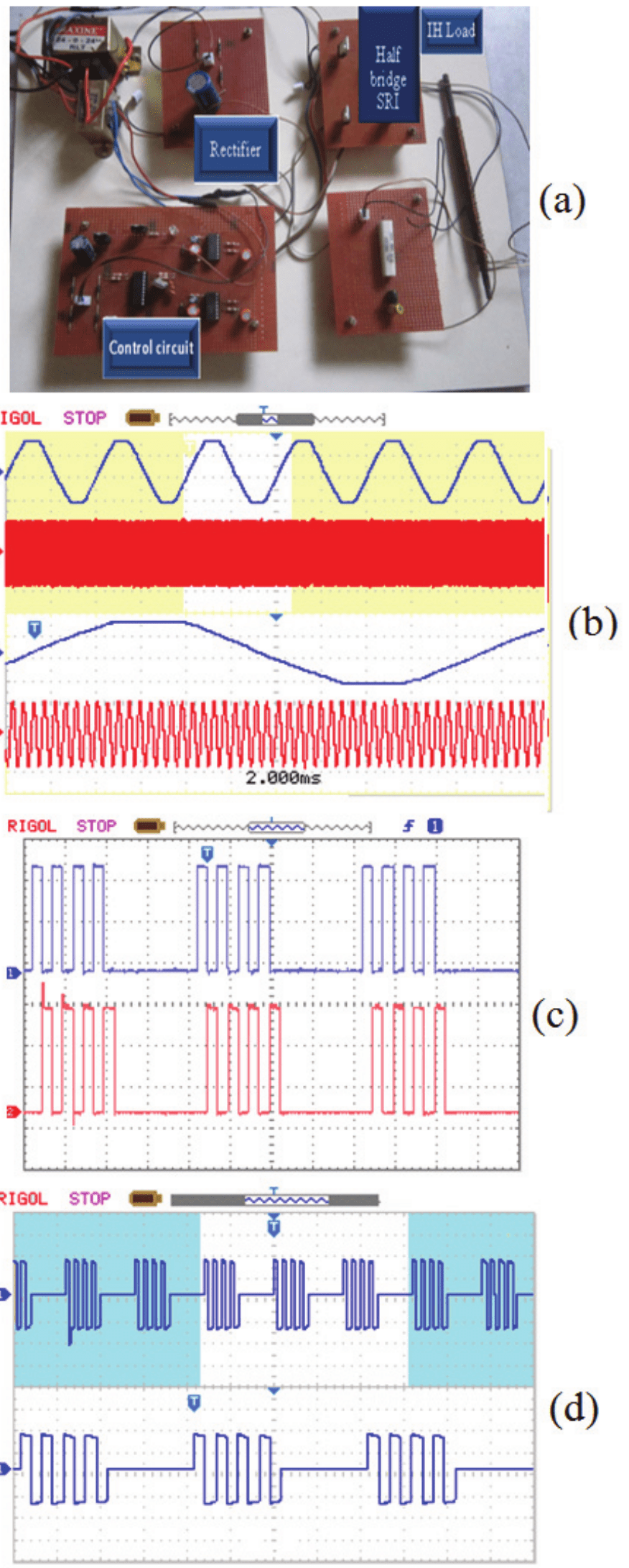
Figure 11
(a) Hardware layout of embedded based fixed frequency ZVS pulse mask controlled HFAC converter; (b) 50 Hz AC and HFAC voltage with 100% DM (4 ms div-1, 15 V div-1); (c) Driver output pulses to Q1 and Q2 with 10% DPM (100 µs div-1, 2 V div,-1); (d) Output Voltage (Vo) (15 V div-1, 50 µs div-1).
The FFT of the utility current with the proposed conversion circuit with and without T filter obtained in the simulation is presented in Figure 14 (a and b), respectively. The presence of input side T filter reduces THD from 27.03 to 2.68%. Thus, the developed pulse masked controlled HFAC voltage fed SRI for IH application had lesser THD and higher output power than the conventional one.
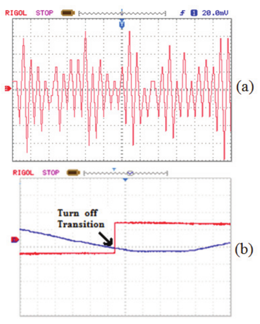
Figure 12.
Hardware results at 10% DM (a) Output current (Io) (200 µs div-1, 2 A div-1); (b) Voltage across the switch (VQ1) and current through the switch (IQ1) at 10% DM (10 µs div-1, 2 A div-1).
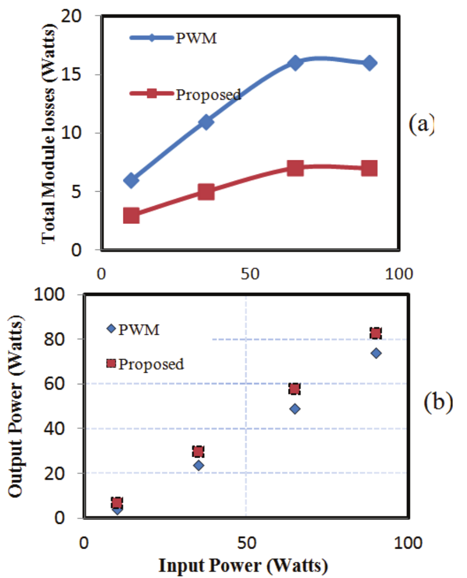
Figure 13
(a) Total losses Vs input power and (b) Output power Vs Input power.
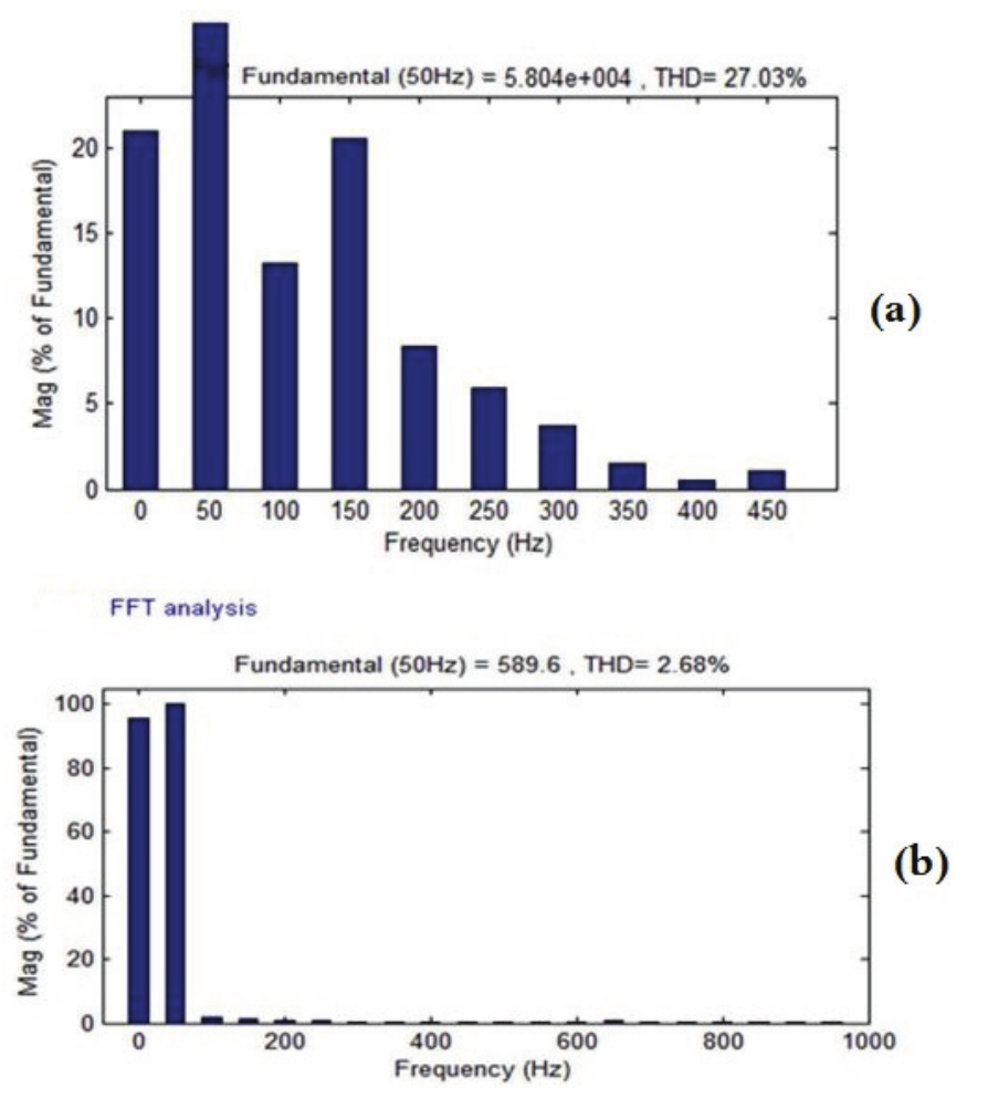
Figure 14
(a) FFT spectrum of supply current without T filter and (b) FFT spectrum of supply current with T filter.
Conclusion
In this paper, constant frequency Pulse mask controlled HFAC power conversion circuit for IH load has been designed, simulated and implemented. The pulse mask control strategy for the HFAC power converter provides ZVS condition for wide-operating range. This converter has advantages, as improved output power with reduced switching losses, linear power variation and low total harmonic distortion. The proposed converter was successfully implemented in hardware using the low cost embedded controller. The hardware results are in good agreement with the simulation results. Further studies should be performed by using phase locked loop based controller for tracking the changes in the load parameters.
References
Acero, J., Burdio, J. M., Bagan, L. A., Navarro, D., Alonso, R., Garcia, J. R., ... Garde, I. (2008). The domestic induction heating appliance: An overview of recent research. Proceeding of Applied Power Electronics Conference and Exposition,conference, 651-657.
Ahmed, N. A., & Nakaoka, M. (2006). Boost-half-bridge edge resonant soft switching PWM high-frequency inverter for consumer induction heating appliances. IEE Proceedings of Electric Power Applications, 153(6), 932-938.
Booma, N., & Ramareddy, S. (2013). Design and simulation of energy efficient fixed frequency pulse controlled power converter for induction melting application. Advanced Materials Research, 768(1), 404-410.
Byun, J. K., Choi, K., Roh, H. S., & Hahn, S. Y. (2000). Optimal design procedure for a practical induction heating cooker. IEEE Transactions on Magnetics, 36(4), 1390-1393.
Carretero, C., Lucia, O., Acero, J., & Burdio, J. M. (2011). Phase-shift control of dual half-bridge inverter feeding coupled loads for induction heating purposes. Electronics Letters, 47(11), 670-671.
Lucia, O., Acero, J., Carretero, C., & Burdio, J. M. (2013). Induction heating appliances: towards more flexible cooking surfaces. IEEE Industrial Electronics Magazine, 7(3), 35-47.
Lucía, O., Barragan, L. A., Burdío, J. M., Jiménez, O., Navarro, D., & Urriza, I. (2011). A versatile power electronics test-bench architecture applied to domestic induction heating. IEEE Transactions on Industrial Electronics, 58(3), 998-1007.
Lucia, O., Burdio, J. M., Barragán, L. A., Acero, J., & Carretero, C. (2011). Series resonant multi-inverter with discontinuous-mode control for improved light-load operation. IEEE Tranactions on Industrial Electronics, 58(11), 5163-5171.
Lucia, O., Burdio, J. M., Millan, I., Acero, J., & Barragán, L. A. (2010). Efficiency oriented design of ZVS half-bridge series resonant inverter with variable frequency duty cycle control. IEEE Transactions on Power Electronics, 25(7), 1671-1674.
Lucia, O., Burdio, J. M., Millan, I., Acero, J., & Puyal, D. (2009). Load-adaptive control algorithm of half-bridge series resonant inverter for domestic induction heating. IEEE Transactions on Industrial Electronics, 56(8), 3106-3116.
Lucia, O., Carretero, C., Palacios, D., Valeau, D., & Burdío, J. M. (2011). Configurable snubber network for efficiency optimization of resonant converters applied to multi-load induction heating. Electronics Letters, 47(17), 989-991.
Meng, L., Cheng, K. W. E., & Chen, K. W. (2011). Systematic approach to high power and energy-efficient industrial induction cooker system: Circuit design, control strategy, and prototype evaluation. IEEE Transactions on Power Electronics, 26(12), 3754-3365.
Park, N. J., Lee, D. Y., & Hyun, D. S. (2007). A power-control scheme with constant switching frequency in class-D inverter for induction-heating jar application. IEEE Transactions on Industrial Electronics, 54(3), 1252-260.
Pham, H., Fujita, H., Ozaki, K., & Uchida, N. (2011). Phase angle control of high-frequency resonant currents in a multiple inverter system for zone-control induction heating. IEEE Transactions on Power Electronics, 26(11), 3357-3366.
Saha, B., Kurl, K. S., Ahmed, N. A., Omori, H., & Nakaoka, M. (2008). Commercial frequency AC to high frequency AC converter with boost-active clamp bridge single stage ZVS-PWM inverter. IEEE Transactions on Power Electronics, 23(1), 412-419.
Sarnago, H., Lucia, O., Mediano, A., & Burdio, J. M. (2013a). Modulation scheme for improved operation of a RB-IGBT based resonant inverter applied to domestic induction heating applications. IEEE Transactions on Industrial Electronics, 60(5), 2066-2073.
Sarnago, H., Lucia, O., Mediano, A., & Burdio, J. M. (2013b). Class-D/DE dual mode-operation resonant converter for improved-efficiency domestic induction heating system. IEEE Transaction on Power Electronics, 28(3), 1274-1285.
Sarnago, H., Mediano, A., & Lucia, O. (2012). High efficiency AC-AC power electronic converter applied to domestic induction heating. IEEE Transactions on Power Electronics, 27(8), 3676-3684.
Author notes
booma_nagarajan@yahoo.com