Engenharia Civil
Mechanical analysis of a shear-cracked RC beam
Análise mecânica de uma viga de concreto armado rompida por cisalhamento
Mechanical analysis of a shear-cracked RC beam
Acta Scientiarum. Technology, vol. 39, no. 3, pp. 285-290, 2017
Universidade Estadual de Maringá

This work is licensed under Creative Commons Attribution 4.0 International.
Received: 30 October 2015
Accepted: 05 August 2016
Abstract: Shear crack analysis is essential for engineers to estimate repair work in concrete structures. So far, conventional theoretical and numerical analyses in fracture mechanics have been applied to study concrete flexural beams, but there is still little knowledge regarding the shear capacity for beams with a diagonal initial notch. In this study, a theoretical analysis is presented to obtain fracture resistance in a four-point RC beam with two inclined initial notch on supports. Here, a fictitious crack approach is adopted for estimating the equivalent effect of the fracture process zone of concrete in shear-cracked. Based on equilibrium equation in the beam notch cross section, shear force was expressed in terms of fracture process zone length. Then, in a double notch four-point beam, Mode II of the stress intensity factor due to the external load is determined. Finally, this process presents the relationship between the shear capacity and the fracture process zone length and expresses the fracture resistance as a function of fracture process zone length.The predicted results of loading capacities are then shown.
Keywords: FPZ, fracture, shear, stress intensity.
Resumo: A análise de cisalhamento é essencial para que os engenheiros estimem o trabalho de reparo em estruturas de concreto. Até agora, análises teóricas e numéricas convencionais em mecânica da fratura foram aplicadas para estudar vigas de flexão de concreto, mas ainda há pouco conhecimento sobre a capacidade de cisalhamento de vigas com um entalhe inicial em diagonal. Este estudo apresenta uma análise teórica para obter resistência à fratura em uma viga de concreto armado de quatro pontos com dois entalhes iniciais inclinados em suportes. Aqui, adota-se uma abordagem de fissura fictícia para estimar o efeito equivalente da zona de processo de fratura (ZPF) do concreto em cisalhamento. Com base na equação de equilíbrio na secção transversal do entalhe da viga, a força de cisalhamento foi expressa em termos de comprimento da zona de processo de fratura. Em seguida, numa viga de quatro pontos com entalhe duplo, determina-se o modo II do fator de intensidade de tensão devido à carga externa. Finalmente, este processo apresenta a relação entre a capacidade de cisalhamento e o comprimento da zona de processo de fratura e expressa a resistência à fratura em função do comprimento da zona de processo de fratura. Os resultados previstos das capacidades de carga são então apresentados.
Palavras-chave: ZPF, fratura, cisalhamento, intensidade de tensão.
Introduction
Fracture mechanics is a branch of solid mechanics, which deals with the behavior of the material and conditions in the vicinity of a crack (Shahbazpanahi, Ali, Aznieta, Kamgar, & Farzadnia, 2013a).The concept of fracture mechanics was first used for pre-cracked concrete structures in the early 1960s (Shahbazpanahi, Abang, Kamgar, & Farzadnia, 2014). Concrete structures are prone to crack propagation. As of now, the fracture process has become a fundamental concept in fracture mechanics of concrete. The first investigation of concrete structure based on fracture mechanics was conducted proposed by Hillerborg, Modeer, & Petersson (1976). This study introduced a region, often termed fracture process zone (FPZ), which as the ability to transfer normal and shear stresses to close the crack (Shahbazpanahi, Ali, Aznieta, Kamgar, & Farzadnia, 2013b; Dong, Wu, Zhou, Dong, & Kastiukas, 2017). The closure stress associated with cracks is a maximum at the tip of the FPZ and decreases to zero at the continuous crack tip where the crack opening reaches its critical value, beyond which an open crack forms (Dong et al., 2016). Since a significant amount of energy is stored in the FPZ, a crack can have stable growth before the peak load (Simon & Kishen, 2017). The energy consumed in this process is the fracture energy required for creating a new crack surface (Brake & Chatti, 2013; Dai & Ng, 2014; Ohno, Uhi, Ueno, & Ohtsu, 2014).
Based on the theory of linear elastic fracture mechanics (LEFM), a fairly high coefficient is applied to the stress in the vicinity of the crack tip. This coefficient is called stress intensity factor. The LEFM converts stress to a unique form of distribution. The stress intensity factor depends on the material properties, on the size of the crack, on the load, and on the geometry of the structure. This factor presents a relationship between the material and the reaction of the structure. Numerous researchers have aimed to calculate stress intensity factor in concrete structure using experimental, analytical and numerical methods (Dong, He, & Wu, 2011; Ooi & Yang, 2011; Ray & Kishen, 2014).
There have also been numerous studies on predicting the influence of FPZ (Xu, Wu, Zheng, Zhao, & Liu, 2011; Wu, Rong, Zheng, & Xu, 2011; Guo, Su, & Young, 2012) and on flexural crack using different methods. However, the effect of FPZ on shear crack has not been studied. Studying stress intensity factors in shear cracks is particularly significant as concrete is usually weak in shear. The present theoretical study focuses on stress intensity factor in RC beam with double incline notches to determine the critical crack length and the fracture toughness in a shear crack.
Here, the objective is to develop of an analytical method to calculate the effect of FPZ on shear cracks in RC beam based on the fictitious crack approach. In the present study, a four-point load RC beam with two incline initial notches on supports is analysed to obtain shear capacity.In linear fracture mechanics, the FPZ at the tip of the crack is considered as the base of a fictitious crack to obtain shear stress distribution in the crack cross section. Interaction between the shear stress distribution and the normal stress in damage zone is used to estimate the cohesive stress of the fracture. Based on the equilibrium equation in the notch cross-section, the change of the shear force versus the FPZ length are determined. Then, Mode II of the stress intensity factor in a double notch four-point beam due to the external load is determined. The fracture resistance of the material is expressed in terms of the fracture toughness of the plain concrete and the shear stress due to the FPZ. Finally, the relationship between the shear capacity and the FPZ length is used to express the fracture resistance as a function of the FPZ length.
Material and methods
Equilibrium equation of the shear-cracked beam
Let us consider a simply supported RC beam under two concentrated load. In the fracture mechanics theory, this beam is called four-point loading RC beam. Shear cracks appear along the shear span in an intermediate position between the loading point and the support depending on the amount of longitudinal reinforcement. Initially, a shear crack follows a vertical trajectory and then turns toward the loading point. However, in the present study, shear crack is induced using an initial notch in the support. Given that the shear force is large and the flexural moment in the support is small, this moment can be ignored when analysing shear cracks in Mode II. The shear crack angle has an important effect on the shear capacity and on the fracture resistance. Actual shear crack angles are seldom reported, but an angle of 45° was used to design RC be arms. Thus, the assumption that the shear crack is at 45° and starts from the support is not far from reality. Figure 1 shows a beam with two inclined initial notches at the shear crack angle of 45º on the support. The four-point loading RC beam has a rectangular cross-section, and the length of the initial notch is a0. Figure 2 indicates that crack grows to ‘a’ due to the extended FPZ if load is increased, where lp, a(σ=0) and ‘a’ are the FPZ length, the stress-free region length and the effective crack length, respectively. The shear strength Vn of the beam is given by (Equation 1):

Equation 1
Equation 1
where: VC and VFPZ are the shear strength contributions of the concrete; FPZ, respectively.
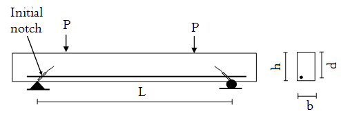
Figure 1
Figure 1. Four-point loading RC beam with two notch’s.
For members under flexure and shear load, the following simple formula for shear strength contribution of the concrete, (American Concrete Institute, 2007) is used (Equation 2):
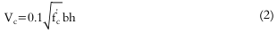
Equation 2
Equation 2
where:
‘fc’ is the compressive strength,
‘h’ and ‘b’ are the depth and the thickness of the beam, respectively. Equation (2) is the expression for concrete shear strength with reinforcement.
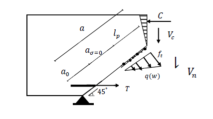
Figure 2
Figure 2. Across section at the cracked and stress distribution.
The normal force due to the cohesive fracture zone is expressed as:
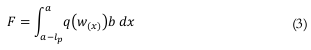
Equation 3
Equation 3
Where: q(w(x)) is the distribution of the stress in the FPZ and w(x) is one-half of the crack opening where the origin of x lies (Figure 2). This means that the normal stress depends on the opening of the crack and the damage zone is still capable to sustain load. Although several complex distributions of stress are available, an simple linear curve is used in the present study. However, an exact expressions of the FPZ stress is especially not easy and the use of these functions are limited.
On the other hand, the interaction between the shear stress distribution and the normal stress in the damage zone was derived by Jefferson (2002) and Koutromanos and Shing (2012).
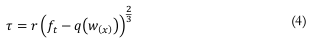
Equation 4
Equation 4
Where: ft is tensile strength of concrete and the factor ‘r’ is given by (Equation 5):

Equation 5
Equation 5
Equation (4) was obtained by computing the strength envelope of the consecutive Mohr’s circles of stress. The load ‘P’ applied to the beam with equilibrium equation is expressed as:
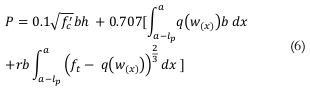
Equation 6
Equation 6
Using Equation (6), the shear capacity can be determined when is known. The shear capacity of the beam is obtained based on the shear strength of concrete, and the shear and normal stresses provided by the cohesive zone. Fracture resistance of the crack will be obtained in the next section by applying the Equation (6). With the assumption that the cross-section in mid-span is un-cracked, the deflection can be obtained by conventional formula for a four-point load beam with simple support.
Fracture resistance of crack
Since shear force prevails the flexure moment in the shear span, a sliding mode (Mode II) is developed. In the present study, Mode II is used to formulate the fracture resistance of the crack. A crack will grow if the stress intensity factor, due to the external load, reaches the fracture resistance of the material, , i.e., (Equation 7)

Equation 7
Equation 7
The stress intensity factor of Mode II for the double notch four-point beam due to the external load P, is given by (Guryao, 1996) (Equation 8):
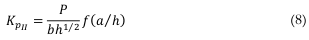
Equation 8
Equation 8
Where ‘b’ and f (a/h) are the thickness of the beam and the geometric shape function, respectively. In which (Equation 9)
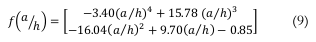
Equation 9
Equation 9
The material fracture resistance is given by (Equation 10):

Equation 10
Equation 10
where and are the plain concrete fracture toughness for Mode II and the toughness due to the shear stress of the fracture process zone, respectively. The shear stress toughness is given by (Zheng, Dai, & Fan, 2016) (Equation 11):

Equation 11
Equation 11
Where (Equation 12):
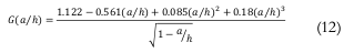
Equation 12
Equation 12
The fracture toughness is the fracture resistance at a special crack length. Thus, the critical crack length is defined numerically by (Equation 13):
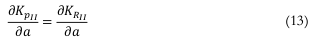
Equation 13
Equation 13
Substituting Equation (8 and 10) into Equation (7 and 13) and then solving the equation, the critical crack length can be obtained. The fracture toughness can be determined using Equation (10) or (11) if the critical crack length is known.
Results and discussions
A simply supported beam without shear reinforcement under four-point bending is considered to validate the proposed theoretical method (Walraven, 1978). This shear beam has since become a benchmark for crack propagation analysis using FEM. The length, the depth, the width, the concrete modulus of elasticity, and the compressive strength are 3520 mm, 450 mm, 200 mm, 28 Gpa and 34.2 Mpa , respectively. The steel bars have 2100 GPa and 600 mm2 elastic modulus and cross-sectional area, respectively. The plain concrete fracture toughness for shear is 5.5 Mpa mm0.5.
Figure 3 shows a comparison of the experimental and the proposed theoretical method between the load ‘P’ and the deflection at mid-span with the assumption that a0 = 0. To calculate the deflection at mid-span, the section is assumed to be un-cracked. The deflection at mid-span of the beam is calculated by the basic principles of mechanics of elastic structures. Therefore, deflection at mid-span is:
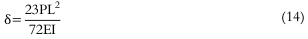
Equation 14
Eqution 14
where: ‘I’ is the moment of inertia of the transformed section. The result of the present study was slightly higher than the experimental observation (approximately 8%). This error was acceptable because crushing, nonlinear behavior of the bulk concrete, yielding of the reinforcement, the bond slip between the concrete and steel, and the plastic deformation were neglected in the theoretical method. The result of the ABAQUS FEA software was considerably higher than the experimental observation (16 to 27%). In the early stage, yielding occurs at approximately 20 k N in the experimental result, but not in the present model. Figure 4 illustrates finite element mesh the crack path modelled by the ABAQUS software for the beam with 6882 C3DBR S4R (average size of 15 X 15 mm) elements.
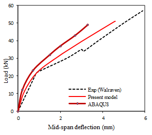
Figure 3
Figure 3. Comparison load vs. deflection in experimental (Walraven, 1978), ABAQUS software and present model.
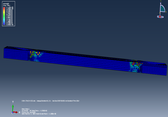
Figure 4
Figure 4. Crack paths of the beam by ABAQUS software.
Figures 5 and 6 show the effects of various parameters, such as the FPZ length and the compressive strength of concrete, on the fracture resistance. Figure 5 shows the relationship between fracture resistance and the effective crack length with three FPZ lengths. The fracture resistance increases with the effective crack length and the FPZ length. The increase in the fracture resistance was slow at the initial stage. Fracture resistance increases quickly as the effective crack length increases because extra load was needed to prevent shear crack growth. Crack propagation was arrested after its growth to a certain position. This finding indicates that, when the effective crack length turns to the beam depth, the fracture resistance approaches infinity. Moreover, the FPZ has a significant role in the fracture toughness of the shear crack. Fracture resistance increases as the FPZ length increases. The FPZ has a significant role in arresting the shear crack similar to the flexural crack.
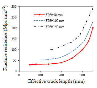
Figure 5
Figure 5. Fracture resistance versus effective crack length and influence FPZ length.
Figure 6 shows the fracture resistance as the FPZ length varied with different compressive strengths of the concrete for the shear crack. Fracture toughness increases with compressive strength concrete based on the FPZ length.
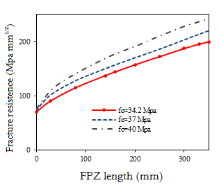
Figure 6
Figure 6 Fracture resistance versus FPZ length with different compressive strength
The growth was 8.5 to 22%. For example, if the compressive strength of the concrete increases from 34.2 to 40 MPa, then the fracture toughness will increase from 157.1 MPa mm1/2 to 191.8 MPa mm1/2. When the compressive strength increases to 40 MPa, the fracture resistance initially increases insignificantly and then increases rapidly. This finding was partially verified by a theoretical method in the fracture for the flexure crack. Thus, the FPZ played a significant role in increasing the fracture resistance of shear crack. The FPZ plays a major role in preventing the propagation of the shear crack because it prevents the propagation of flexural crack.
Figure 7 shows the variation of the load, which is given as a the stress-free region length in the current study with different concrete compressive strengths at mm. The load increases with the decrease in the compressive strength when the FPZ length fully develops; this finding is similar to that in the flexure crack. Moreover, when FPZ length fully develops ( mm), the length of the stress-free region appears ahead of the notch tip and expands to the top of the beam (Wu et al., 2011).
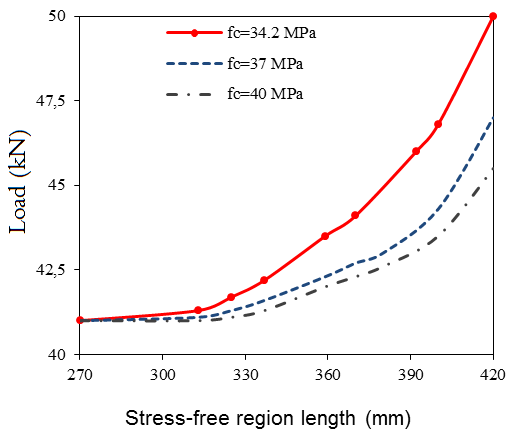
Figure 7
Figure 7. Load vs. stress-free region length with different concrete compressive strength.
Conclusion
A new theoretical procedure is proposed for determining the shear capacity and the fracture resistance of shear–cracked concrete beams. Based on the equilibrium equation in the notch cross-section, the shear force is expressed in terms of the FPZ length. The fracture toughness of the RC beam is calculated based on the linear fracture mechanics. Based on the equilibrium equation in the notch cross-section, shear force is expressed in terms of the FPZ length. Then, Mode II of the stress intensity factor in double notch four-point beam due to the external load is determined. The fracture resistance of the materials is explained by the plain concrete fracture resistance and the shear stress due to the FPZ. Finally, the relationship between the shear capacity and the FPZ length is used to express the fracture resistance as a function of the FPZ length. It is observed that the results in the present study are slightly (approximately 8%) higher than those of previous experimental observations. It is also observed that the FPZ had a positive and significant influence on the fracture toughness and in preventing the propagation of shear cracks. The proposed method considers the effect of the geometric parameters and shows acceptable similarity to the experimental data ABAQS software data.
References
American Concrete Institute [ACI]. (2007). Building code requirements for structural concrete (ACI 318). Armington Hills, MI: ACI.
Brake, N. A., & Chatti, K. (2013). Prediction of size effect and non-linear crack growth in plain concrete under fatigue loading. Engineering Fracture Mechanics, 109(1), 169-185.
Dai, Q., & Ng, K. (2014). 2D cohesive zone modeling of crack development in cementitious digital samples with microstructure characterization. Construction and Building Materials, 54(1), 584-595.
Dong, W., He, H. N., & Wu, Z. M. (2011). Experimental and numerical study on mode I-II crack propagation for small size specimens of concrete. Advanced Materials Research. 163-167(1), 908-912.
Dong, W., Wu, Z., Zhou, X., Dong , L., & Kastiukas, G. (2017). FPZ evolution of mixed mode fracture in concrete: Experimental and numerical. Engineering Failure Analysis. 75, 54-70.
Dong, W., Yang, D., Kastiukas, G., & Zhang, B. (2016). Experimental and numerical investigations on fracture process zone of rock–concrete interface. Fatigue and Fracture of Engineering Materials and Structures. 40(5), 820-835.
Guo, X., Su, R. K., & Young, B. (2012). Numerical investigation of the bilinear softening law in the cohesive crack model for normal-strength and high-strength concrete. Advances in Structural Engineering, 15(3), 373-388.
Guryao, W. (1996). Study of mode II fracture of rock and its engineering application. Changsha, CN: Centeral South Univercity of Technology .
Hillerborg, A., Modeer, M., & Petersson, P. (1976 ). Analysis of crack formation and crack growth in concrete by means of mechanics and finite element. Cement and Concrete Research, 6(1), 773-782.
Jefferson, D. (2002). Tripartite cohesive crack model. Journal of Engineering Mechanics, 128 (6), 644-653.
Koutromanos, I., & Shing, P. (2012). Cohesive crack model to simulate cyclic response of concrete and masonry structures. ACI Structural Journal, 109 (3), 349-358.
Ohno, K., Uji, K., Ueno, A., & Ohtsu, M. (2014 ). Fracture process zone in notched concrete beam under three-point bending by acoustic emission. Construction and Building Materials, 67(1), 139-145.
Ooi, E. T., & Yang, Z. J. (2011). Modelling crack propagation in reinforced concrete using a hybrid finite element–scaled boundary finite element method. Engineering Fracture Mechanics, 78(2), 252-273.
Ray, S., & Kishen, J. M. (2014). Analysis of fatigue crack growth in reinforced concrete beams. Materials and Structures/Materiaux et Constructions, 47 (1), 183-198.
Shahbazpanahi, S., Abang, A., Kamgar, A., & Farzadnia, N. (2014). Fracture mechanic modeling of fiber reinforced polymer shear-strengthened reinforced concrete beam. Composites Part B Engineering, 68(1), 113-120.
Shahbazpanahi, S., Ali, A. A., Aznieta, F. N., Kamgar, A., & Farzadnia, N. (2013a). A simple and practical model for FRP-reinforced cracked beam. European Journal of Environmental and Civil Engineering, 19(1), p. 293-306.
Shahbazpanahi, S., Ali, A. A., Aznieta, F. N., Kamgar, A., & Farzadnia, N. (2013b). Modelling of the fracture process zone to improve the crack propagation criterion in concrete. Journal of the South African Institution of Civil Engineering, 55(3), 2-9.
Simon, K. M., & Kishen, J. M. (2017). A multiscale approach for modeling fatigue crack growth in concrete. International Journal of Fatigue, 98, 1-13.
Walraven, J. (1978). The infuence of depth on the shear strength of lightweight concrete beams without shear reinforcement. Delf, NL: Delft University of Technology.
Wu, Z., Rong, H., Zheng, J., & Xu, F. (2011). An experimental investigation on the FPZ properties in concrete using digital image correlation technique. Engineering Fracture Mechanics, 78(17), 2978-2990.
Xu, F., Wu, Z., Zheng, J., Zhao, Y., & Liu, K. (2011). Crack extension resistance curve of concrete considering variation of FPZ length. Journal of Materials in Civil Engineering, 23(5), 703-710.
Zheng, J., J., Dai, J., G. & Fan, X. L. (2016). Fracture analysis of FRP-plated notched concrete beams subjected to three-point bending. Journal of Engineering Mechanics, 142(3). Doi: 10.1061/(ASCE)EM.1943-7889.0001021
Author notes
sh.shahbazpanahi@iausdj.ac.ir