Engenharia Civil
A comparative experimental investigation of reinforced-concrete pipes under three-edge-bearing test: Spigot and Pocket and Ogee Joint pipes
Investigação experimental de tubos de concreto armado submetidos ao ensaio de compressão diametral: tipo ponta e bolsa e macho-fêmea
A comparative experimental investigation of reinforced-concrete pipes under three-edge-bearing test: Spigot and Pocket and Ogee Joint pipes
Acta Scientiarum. Technology, vol. 40, 2018
Universidade Estadual de Maringá

This work is licensed under Creative Commons Attribution 4.0 International.
Received: 09 February 2016
Accepted: 03 May 2016
Abstract: An experiment on the behavior of two types of circular reinforced concrete pipes under three-edge-bearing test is analyzed and discussed. Current study compares the strength of spigot-pocket (SPP) and ogee joint pipes (OJP). In the experimental analyses thirty-two pipes, nominal diameter 800 and 1200 mm, divided into two series of 16 pipes each, were tested. Each series was composed of 12 spigot-pocket pipes (SPP) and 4 ogee joint pipes (OJP). Experimental results of the loading versus displacement curves indicated that pipes behave similarly to a circular ring, since the OJP presented maximum loads 12 and 4% higher than those obtained for SPP respectively for nominal diameters 800 and 1200 mm. Pocket influenced load cracking, with 6.4 and 33% higher for SPP when compared to OJP for nominal diameters 800 and 1200 mm, respectively. Further, the presence of the pocket increased the pipe´s stiffness.
Keywords: nominal diameter, circular ring, load cracking, stiffness.
Resumo: Esta pesquisa apresenta um estudo experimental sobre o comportamento de dois tipos de tubos circulares de concreto armado submetidos à compressão diametral. O estudo compara a resistência de tubos do tipo ponta e bolsa (SPP) e macho-fêmea (OJP). Na análise experimental, foram ensaiados 32 tubos divididos em duas séries de 16 tubos de diâmetros nominais de 800 e 1200 mm. Cada série era formada por 12 tubos SPP e 4 tubos OJP. Os resultados experimentais da curva força versus deslocamento indicaram que o tubo se comportou como um anel circular, uma vez que os tubos OJP apresentaram forças últimas da ordem de 12 e 4% maiores que as obtidas para os tubos SPP, para os diâmetros nominais de 800 e 1200 mm, respectivamente. A presença da bolsa influenciou no valor da força de fissuração, sendo 6,4 e 33% maior para os tubos SPP em relação aos tubos OJP para os diâmetros nominais de 800 e 1200 mm, respectivamente. Outra conclusão sobre a presença da bolsa é que ela aumenta a rigidez do tubo.
Palavras-chave: diâmetro nominal, anel circular, força de fissuração, rigidez.
Introduction
Buried reinforced concrete pipes are used worldwide as the main alternative for basic sanitation. Since this type of construction is not visible people´s eyes, it generally receives less attention than other structures. Nevertheless, reinforced concrete pipes should have the same attention, perhaps an even greater one than that given to the structure project (El Debs, 2003).
Marston-Spangler’s procedure on the design of buried pipes is usually employed (Zaidler, 1983). This procedure involves determining the resultant of vertical operating loads on the pipe by using an equivalence factor that correlates the behavior of the pipe in the field and in standard test situations. It is important to emphasize that the failure of a pipe may cause serious and costly problems, even though without any fatal victims.
A highly relevant factor in the improvement of reinforced concrete pipes projects is the fact that a small saving in the production of a pipe unit will result in a wide final saving in the design of a pipeline, due to the number of repetitions of units used within basic sanitation. Some activities are essential to decrease expenditure: premises must be reliable; they must have increasingly smaller work in implementing; construction must be safe; advantages of the site´s native soil must be taken (American Society of Civil Engineering [Asce], 1994).
Research on pipes has provided important contributions related to experimental studies carried out in the laboratory and on the field (Heger, 1963; Deen & Havens, 1964; Altun & Haktanir, 2004; Haktanir, Ari, Altun, & Karahan, 2007; Figueiredo & Chama Neto, 2008). Numerical studies on concrete pipes are extant (Algood, 1972; Silva, El Debs, & Beck, 2008; Fuente, Figueiredo, Aguado, Molins, & Chama Neto, 2011; Fuente, Escariz, Figueiredo, Molins, & Aguado, 2012; Fuente, Escariz, Figueiredo, & Aguado, 2013) in which reinforcement and fiber were analyzed.
However, it is difficult to predict the behavior of a structure with a large number of design parameters. it is not different in the case of circular reinforced concrete pipes and the prediction of their behavior may be far from the real thing, since
a) The strength of the cross section is strongly affected by the variation of the position of the steel bars and by the wall thickness;
b) The loading to which the pipes are subjected is affected by conditions of installation, because there are uncertainties on responses, especially with regard to the hypotheses of the soil behavior;
c) Reinforcement is calculated by assessing the resistance of the wall. The addition of resistance due to spigot and pocket at the end of one side of the pipe is neglected;
d) Pipes are designed to withstand an expected situation in standardized tests. The equivalent coefficient, or rather, the difference between this situation and the installation´s current condition, may be analytically determined or calculated by the distribution of pressures based on experimental measurements.
Current paper presents an experimental study on the behavior of circular reinforced concrete pipes under three-edge-bearing test (diametrical compression test). Some aspects, such as maximum loading and cracking, displacements and deformations, have been analyzed in the tests. Current analysis compares the strength of spigot-pocket and ogee joint pipes to assess quality control of circular reinforced concrete pipes for the specific situation of the diametrical compression test appointed by Brazilian Standards (Associação Brasileira de Normas Técnicas [ABNT], 2007).
The experimental program evaluated the influence of some parameters on the behavior of circular reinforced concrete pipes subjected to diametrical compression. Parameters comprised concrete compressive strength, thickness of the pipe and the position of the reinforcement in the pipe. In the case of spigot-pocket pipes, the influence of the pocket was evaluated based on the assumption adopted in the calculation that the pipes behaved as circular rings.
Based on the results of diametrical compression tests in several pipes, the variability in the structural behavior of these factors and the dispersion of load cracking and failure were investigated. To ensure the reliability of experimental results, all pipes were produced with the same manpower, equipment and materials. They underwent similar environmental conditions and tested at the same age. Finally, the same geometric characteristics were used in their production and flexural reinforcement ratio.
The achievement of the diametrical compression tests followed procedures proposed in Brazilian standards (ABNT, 2007) with regard to the diametrical compression test of circular reinforced concrete pipes for rainwater and sanitary sewers. However, some modifications were carried out in test development to achieve maximum benefit, as will be shown below.
Material and methods
Simple circular reinforcement is usually employed in the design of circular reinforced concrete pipes with less than 1000 mm of nominal diameter, whereas double circular reinforcement is used for diameters greater than 800 mm. Double circular reinforcement is also used when the adoption of simple circular reinforcement results in heavy thicknesses. According to these suggestions, circular pipes with nominal diameters of 800 and 1200 mm were tested in current experiment to evaluate the behavior of the pipes in the two conditions. The Marston-Spangler procedure was employed in pipe design to determine the reinforcement ratio.
The experimental program comprised thirty-two three-edge-bearing tests. Half of the pipes had a nominal diameter of 800 mm (Series 1) and the remaining half featured a 1200 mm diameter (Series 2). In each series, twelve pipes had the pocket (spigot-pocket) and the remaining four pipes were produced without the pocket (ogee joint pipes), henceforth SPP and OJP, respectively. Table 1 and Figure 1 show the pipes´ features.
The position of the displacement transducers was the same in all the tests. Figure 2 illustrates the instrumentation.
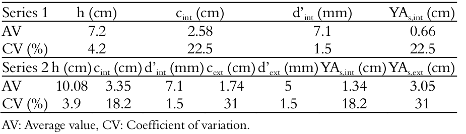
![Characteristics of the tested pipes according to American
Society for Testing and Materials [ASTM] C76 (2016) and ABNT (2007).](../303258327004_gt2.png)
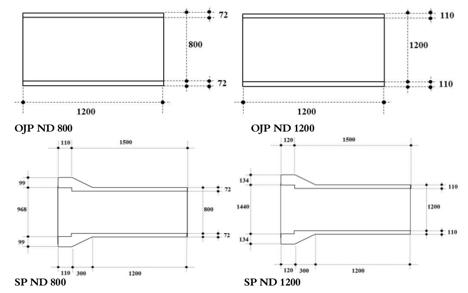
Figure 1.
Dimensions of the pipes (mm).
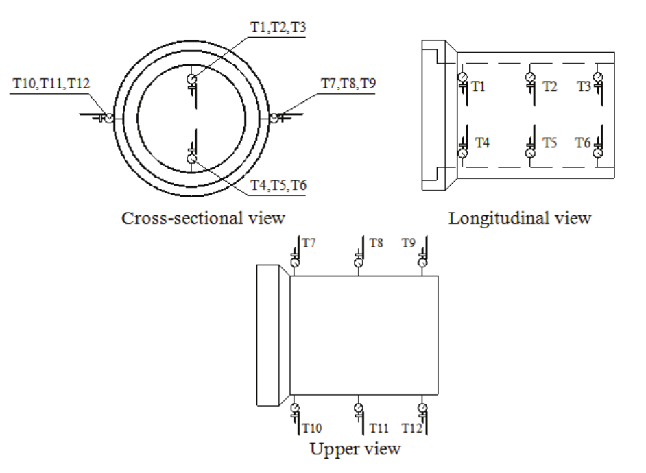
Figure 2.
Instrumentation with Strain Gauges.
Figure 3 shows a steel reaction frame used in the three-edge-bearing tests of the pipes. The tests were conducted according to the predictions of Brazilian code (ABNT, 2007), which are similar to ASTM C497 (2003) and European Standards [EN] 1916 (2002).
In the evaluation of the load crack, loading versus displacement curves and loading versus strain curves were used, which were plotted according to measurements of the displacement transducers and the strain gauges, respectively.
Samples were retrieved from the pipes at the spigot and pocket areas for the characterization of the concrete. Specimens of all tested pipes were extracted by hole saw to define the dimensions at a ratio of 1:2 (diameter: height). The samples provided the evaluation of the actual wall thickness of the pipes at the spigot and pocket areas, and the position of the reinforcement in the mass of concrete. Samples were also subjected to a compressive test to determine the compressive strength of the concrete.
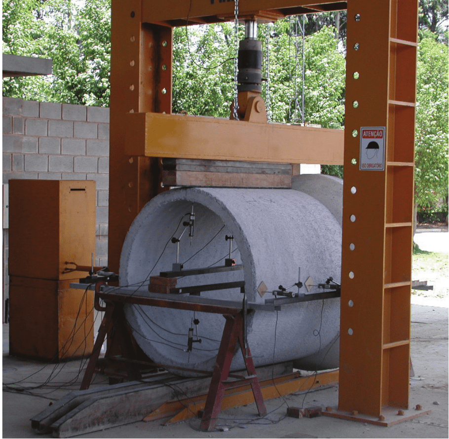
Figure 3.
View of the diametrical compression test.
In addition to the samples extracted from the tested pipes, others were cast to determine the mechanical properties of the concrete. The new specimens were 100 mm in diameter and 200 mm in height.
Sampling of thickness (h), coverings (c) and the positions of reinforcement (YAS) for Series 1 and 2 was carried out by extracting specimens at the spigot and the pocket areas of the pipes. Figure 4 shows these parameters for the specimens with single circular reinforcement arrangement and double reinforcement arrangement. YAs,int and YAs,ext used in Figure 4 represent the internal and external reinforcements, respectively, whilst Table 2 shows the rates of these parameters.
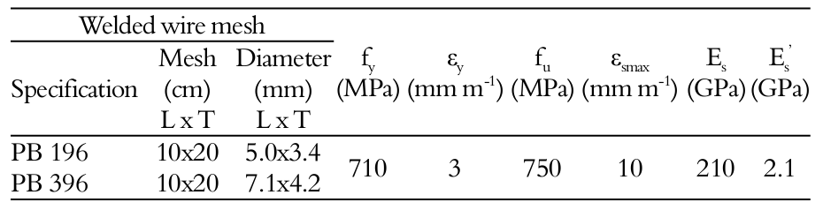
Steel mesh with ribbed steel wire AC-60 (adhesion coefficient ηb = 1.5) was used in the manufacture of the pipes. The mechanical properties of the welded mesh were obtained from tensile tests (Table 3).
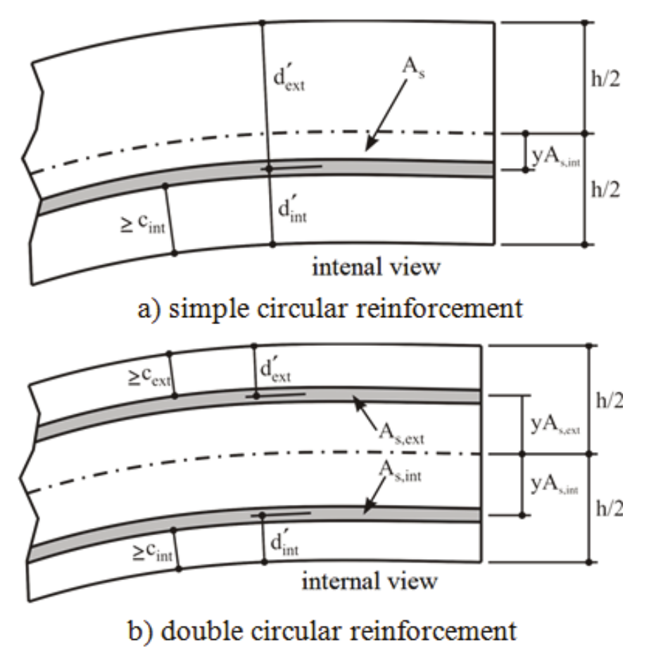
Figure 4.
Reinforcement arrangements.
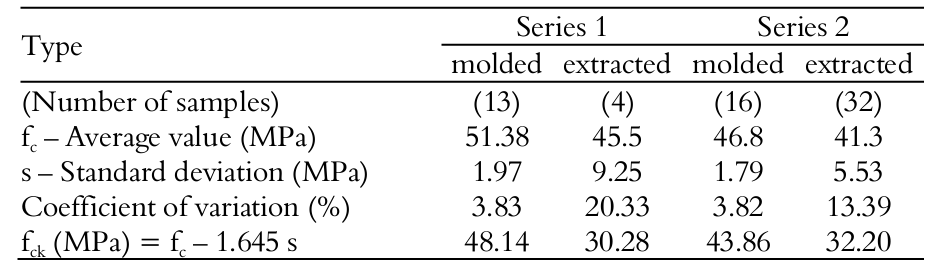
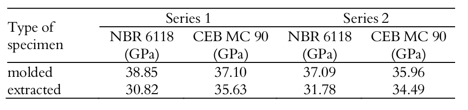
For Series 1, or rather, pipes with nominal diameter of 800 mm, seventeen compression tests were performed to determine the compression strength of the concrete. It should be underscored that four specimens were extracted from the pipes and thirteen were cast in the same condition for the manufacture of the pipes. In Series 2, or rather, pipes with a nominal diameter of 1200 mm, thirty-two specimens were extracted and sixteen specimens were cast. Table 4 shows results of the characterization tests of the concrete. Analysis of rates reveal that in the two series, the variability of the compressive strength for the cast specimens was lower than that for the specimens extracted from the tested pipes.
Eight tensile tests by diametrical compression were carried out for each series of pipes. Two of them were conducted with cast specimens within the same conditions of pipe production and the remaining six were carried out with specimens cast on the vibrating table. The variability of the tensile strengths obtained in the tests is shown in Table 5.
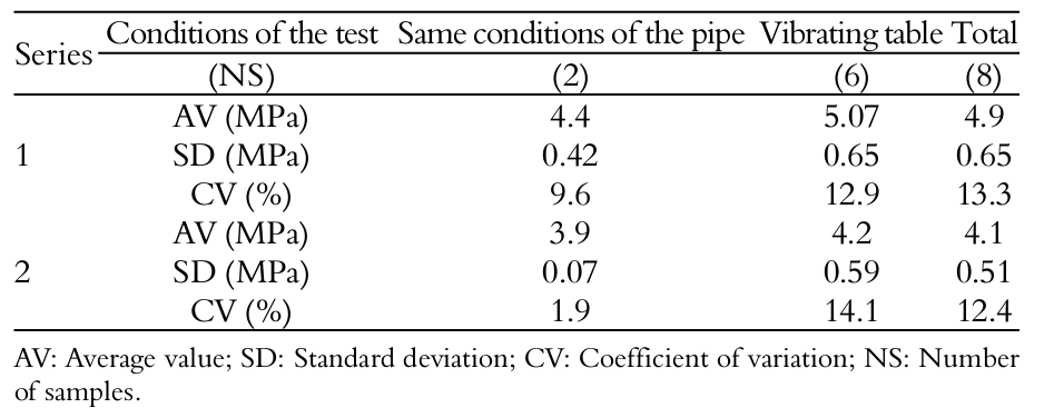
The average rates of compressive strength in the cast condition (Table 4) and the formulation (ABNT, 2014) for the tensile strength demonstrated the tensile strength of the concrete was 3.97 and 3.73 MPa respectively for Series 1 and 2. Rates are close to those in Table 5.
The elasticity modulus was determined by average rates of compressive strength of concrete and the formulations presented in ABNT NBR 8890 (2007) and CEB MC 90 (Comite Euro-International Du Beton., 1990), as shown in Table 6.
Results and discussion
Figure 5 and 6 present loading versus vertical and horizontal displacements curves in the direction of the diameter. Displacements correspond to tests with OJP and SPP pipes of Series 1 and 2, respectively. These measurements were obtained by the sum of the crown displacement, base displacement and flanks displacement, respectively. With regard to the vertical displacement variation, the measurements were defined by the sum of T1+T4, T2+T5 and T3+T6. Taking the horizontal displacement variation into consideration, they were determined by the sum of T7+T10, T8+T11 and T9+T12. The letter T indicates the displacement transducer position during the test (Figure 2).
Figure 5 and 6 demonstrate the loading manner applied on the pipes. Loading was distributed throughout the usable length of the pipes, as shown in Table 1. OJP and SPP pipes were 1.2 and 1.5 m long, respectively. In the case of SPP pipes, the loading was not applied in the region of the pocket as in Figure 7. However, as the region of the pocket is also affected by the loading effect, it is appropriate to divide the loading by the total effective length of the pipe, or rather, 1.5 m for SPP pipes.
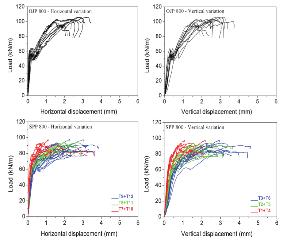
Figure 5.
Load versus displacement of the Series 1.
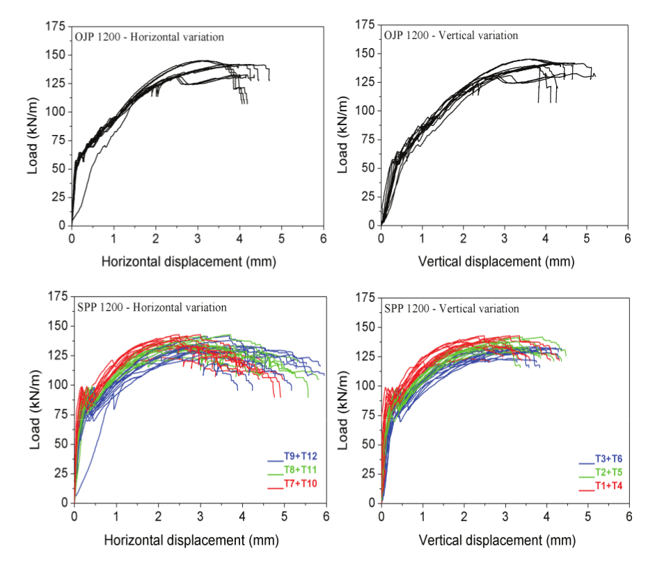
Figure 6.
Load versus displacement of Series 2.
Based on the model in Figure 8 with the vertical and horizontal displacement curves, Table 7 shows the variability (average value - AV and variation coefficient - VC) of the loading values (Fcracking and Fmaximum) for Series 1 and 2, related to Figure 5 and 6. When this kind of decrease is not clear, the load cracking is the first maximum load.
According to results on Table 7, it may be seen that the presence of the pocket did not increase the maximum strength achieved by the Series 1 and 2 pipes. This result was not expected since the pocket provides stiffness to the pipe. By and large, rate dispersion of maximum loading and cracking for OJP and SPP pipes was negligible (coefficient of variation lower than 10%) due to the quality control in the production process of the pipes, which is more rigorous because produced in a factory. For all types of studied pipes, it was observed that the variability of the cracking load (Fcracking) was greater than the rupture load (Fmaximum).
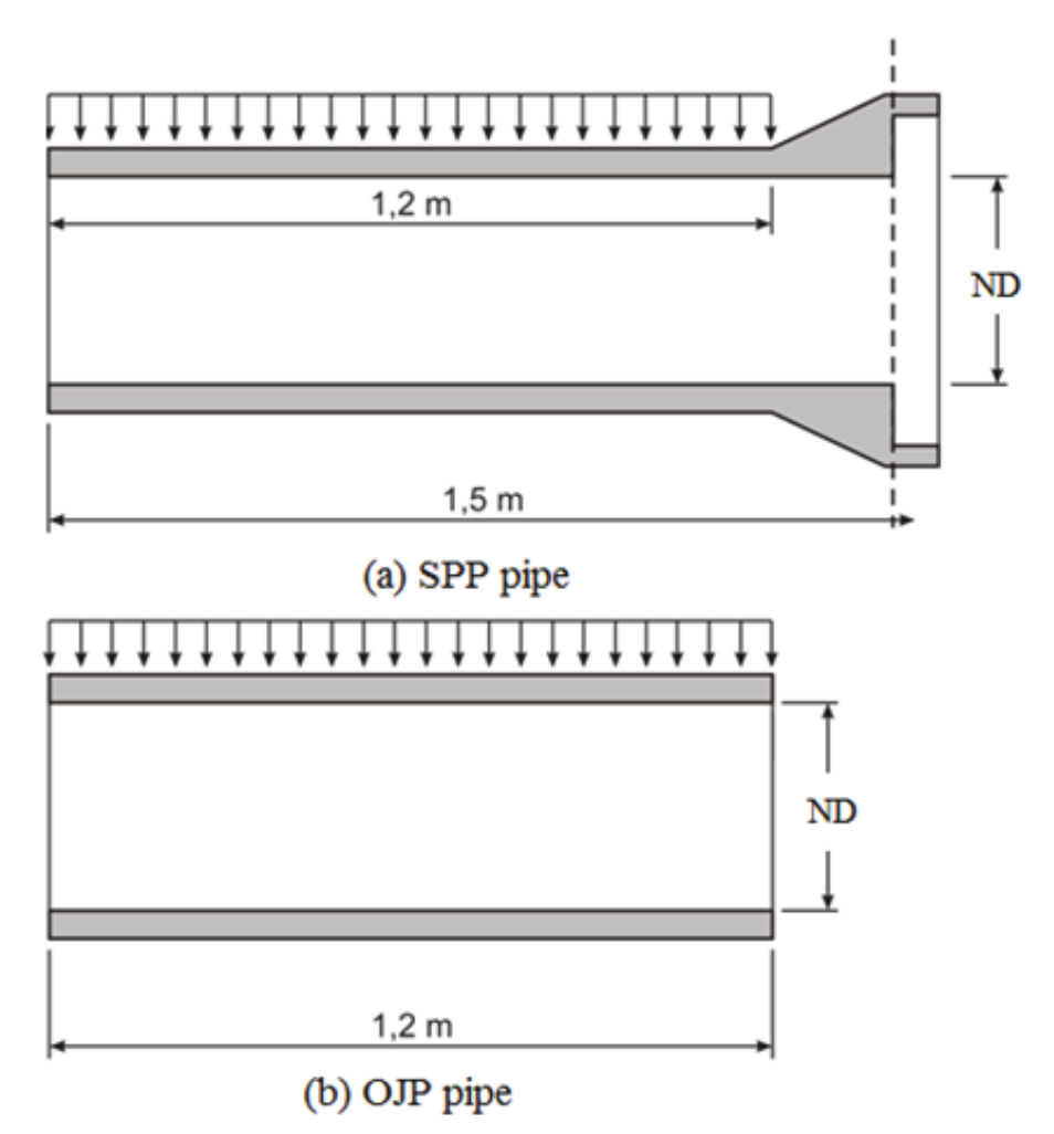
Figure 7.
Application of loading on the pipes.
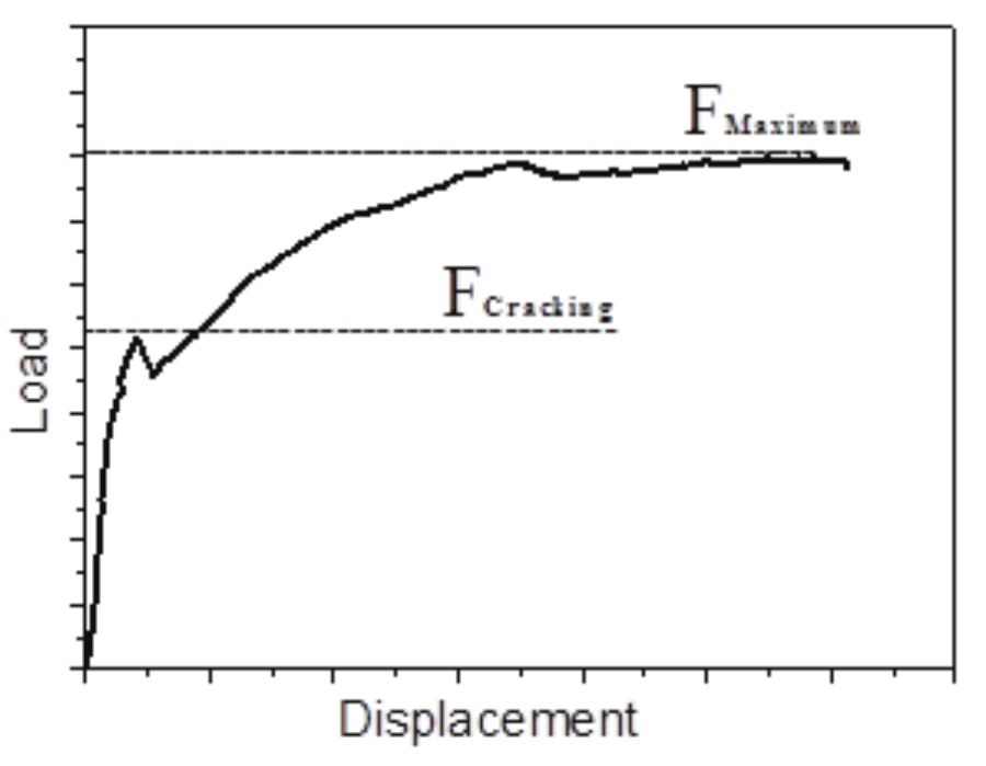
Figure 8.
Typical behavior of pipes subjected to diametrical compression.
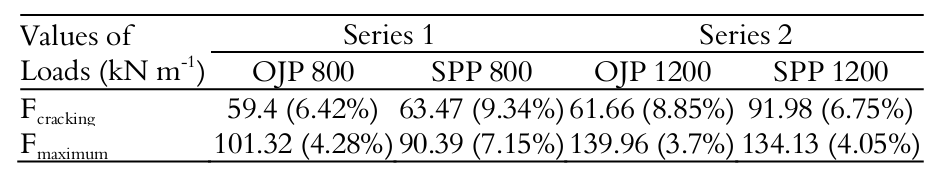
As shown in Table 7, with regards to loading, it must be underscored that the pocket had greater influence on the rate of loading cracking, or rather, 6.4 and 33% greater in the case of SPP pipes for Series 1 and 2, respectively. In the case of maximum loading, OJP pipes presented rates which were 12 and 4% greater than SPP pipes, for Series 1 and 2, respectively. Therefore, in terms of maximum loading, the calculus hypothesis that SPP pipes will behave as a circular ring is valid, due to the fact that the pocket has not been reinforced for such performance, as adopted by El Debs (2003).
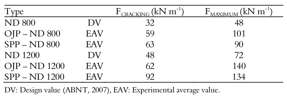
In accordance to ASTM C76 (2016) and ABNT (2007), the minimum loading of failure for the reinforced concrete pipes must correspond to 1.5 of the minimum load cracking. According to Table 7, in the case of Series 1 (nominal diameter 800 mm), the average rate of tensile strength ranges between 1.7 and 1.4 of the average rate of the load cracking for OJP and SPP pipes, respectively. Analyzing the results of the tests of the pipes for Series 2 (nominal diameter 1200 mm), the tensile strength corresponds to 2.3 and 1.46 of the load cracking obtained for OJP and SPP pipes, respectively. It must be underscored that OJP pipes of the two Series reached an increase in strength higher than 50%, unlike what occurred in SPP pipes. However, all pipes reached the minimum load cracking and failure, as Table 8 demonstrates.
In the literature, there are almost no evaluations of the cracking load of the pipes. However, the relationship between the design and experimental values is unknown. Therefore, experimental studies, such as those one presented in this paper, are important references for the technical community.
Figure 9 provides results obtained for cracking and failure situation. Average displacements related to vertical and horizontal variations of the diameter for each series and pipe type, were evaluated, for instance, Series 1 - OJP, Series 1 – SPP, Series 2 - OJP and Series 2 - SPP. Figure 9 shows the variability of the vertical and horizontal diameters for Fcracking and Fmax situations.
Experimental results also indicated that the vertical and the horizontal variations of the diameter obtained in the test of the OJP pipes, for both series, had a low dispersion (coefficient of variation) for displacements corresponding to loading failure (Fmax), unlike to what occurred in displacements corresponding to load cracking (Figure 9). These results are most evident in Series 2 pipes, which present coefficient of variation less than 5% for Fmax. Taking the analysis of OJP pipes into consideration, due to the displacement with slight dispersion along this type of pipe, this conclusion validates the hypothesis that pipes behave like circular rings, as adopted by normative recommendations for design phase (El Debs, 2003).
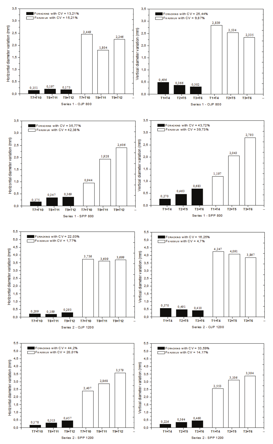
Figure 9.
Variability of displacement rates of Series 1 and 2.
Conclusion
The main conclusions in current research are:
a) The hypothesis for maximum loading is validated, or rather, that pipes behave as circular rings since OJP presents maximum loads which are 12 and 4% higher than those obtained for SPP respectively for nominal diameters 800 and 1200 mm.
b) The pocket influenced the load cracking at 6.4 and 33% higher for SPP when compared to OJP, respectively for nominal diameters 800 and 1200 mm.
c) When displacements are considered, the pocket increases stiffness and, therefore, a significant decrease in displacement rates in the areas close to the pocket at the moment of the initial opening of the cracks and in failure (ultimate strength).
Acknowledgements
The authors would like to thank Conselho Nacional de Desenvolvimento Científico e Tecnológico (CNPq) and Coordenação de Aperfeiçoamento de Pessoal de Nível Superior (CAPES) for funding current research. Thanks are also due to Fermix Indústria e Comércio Ltda for donating the concrete pipes and for its support in conducting the tests.
References
Algood, J. R. (1972). Summary of soil-structure interaction. Port Hueneme, CA: Naval Civil Engineering Laboratory.
Altun, F., & Haktanir, T. (2004). A comparative experimental investigation of steel fibre added reinforced concrete beams. Materiales de Construcción, 54(276), 5-15.
American Society for Testing and Materials [ASTM]. (2003). ASTM-C497-03a: Standard Test Methods for Concrete Pipe, Manhole Sections, or Tile. Houston, TX: ASTM..
American Society for Testing and Materials [ASTM]. (2016). ASTM-C76-16: Standard Specification forReinforced Concrete Culvert, Storm Drain, and Sewer Pipe. Houston, TX: ASTM.
American Society of Civil Engineering [ASCE]. (1994). Standard practice for direct design of buried precast concrete pipe using standard installations (SIDD). New York City, NY: ASCE.
Associação Brasileira de Normas Técnicas [ABNT]. (2007). NBR 8890: Concrete Pipes for Circular Section for Pluvial Waters and Sanitary Sewers-Requirements and Test Methods. Rio de Janeiro, RJ: ABNT.
Associação Brasileira de Normas Técnicas [ABNT]. (2014). NBR 6118: Design of concrete sctuctures. Rio de Janeiro, RJ: ABNT.
Comite Euro-International Du Beton. (1990). CEB-FIB model code 1990 (CEB MC 90). London, UK: Bulletin d'Information.
Deen, R. C., & Havens, J. H. (1964). Some effects of fabrications practices on strength: characteristics of reinforced concrete culvert pipe. Frankfort, KY: Highway Research Record.
El Debs, M. K. (2003). Design estrutural de tubos circulares de concreto armado. São Paulo, SP: IBTS.
European Standards [EN 1916]. (2002). Concrete Pipes and Fittings, Unreinforced, Steel Fibre and Reinforced. Brussels, BE: European Committee for Standardization.
Figueiredo, A. D., & Chama Neto, P. J. (2008). Mechanical performance evaluation of pipes. Revista DAE, 178(1), 34-39.
Fuente, A., Escariz, R. C., Figueiredo, A. D., & Aguado, A. (2013). Design of macro-synthetic fibre reinforced concrete pipes. Construction and Building Materials, 43, 523-532.
Fuente, A., Escariz, R. C., Figueiredo, A. D., Molins, C., & Aguado, A. (2012). A new design method for steel fibre reinforced concrete pipes. Construction and Building Materials, 30, 547-555.
Fuente, A., Figueiredo, A., Aguado, A., Molins, C., & Chama Neto, P. J. (2011). Experimentation and numerical simulation of steel fibre reinforced concrete pipes. Construction and Building Materials, 61(302), 275-288.
Haktanir, T., Ari, K., Altun, F., & Karahan, O. (2007). A comparative experimental investigation of concrete, reinforced-concrete and steel–concrete pipes under three-edge-bearing test. Construction and Building Materials, 21(8), 1702-1708.
Heger, F. J. (1963). Structural behavior of circular reinforced concrete pipe - Development of Theory. American Concrete Institute Journal, 60(11), 1567-1614.
Silva, J. L., El Debs, M. K., & Beck, A. T. (2008). Reliability evaluation of reinforced concrete pipes in crack opening limit state. Ibracon Structures and Materials Journal, 1(4), 314-330.
Zaidler, W. (1983). Projeto estrutural de tubos enterrados. São Paulo, SP: Pini Publisher.
Notes
Author notes
jefferson@sc.usp.br