Engenharia Civil
Influence of relative stiffness on the behavior of piled raft foundations
Influência da rigidez relativa no comportamento de fundações em radier estaqueado
Influence of relative stiffness on the behavior of piled raft foundations
Acta Scientiarum. Technology, vol. 40, 2018
Universidade Estadual de Maringá

This work is licensed under Creative Commons Attribution 4.0 International.
Received: 03 February 2017
Accepted: 13 June 2017
Abstract: The behavior of piled foundations is influenced by several factors, especially those related to the geometry of the foundations, the number of piles, the height of the element that tops the piles and the type of soil in which the foundations are inserted. Given the various situations and variations of parameters to be analyzed, it is common to use numerical modeling for the analysis of geotechnical engineering problems. The piled rafts in this article are numerically analyzed by means of the three-dimensional finite element method using CESAR-LCPC® v.5 software. Thus, it was possible to conduct various analyses of piled rafts by varying the amount of piles and the thickness of the raft supported on the soil and piles. The results demonstrate that piled raft foundations tend to make displacements uniform, thus minimizing problems with differential settlement in structures. The thickness of the plate of the piled raft influences the load distribution in the piles under the raft when the piles are supported on the ground. The relative stiffness (Krs), which is the ‘stiffness’ of the piled raft combined with the soil, increases with increases in the amount of piles and the thickness of the piled raft.
Keywords: piled raft, numerical analysis, piles, relative stiffness.
Resumo: As fundações estaqueadas tem seu comportamento influenciado por diversos fatores, principalmente àqueles relacionados à sua geometria, quantidade de estacas, altura do elemento que coroa as estacas e o tipo de solo onde está inserida. Diante das diversas situações e variações de parâmetros a serem analisados, é comum o emprego de modelagem numérica para análise dos problemas da engenharia geotécnica. Os radiers estaqueados deste artigo são analisados numericamente pelo método dos elementos finitos 3D com o software LCPC-Cesar® versão 5.0. Neste sentido, foi possível realizar diversas análises de radiers estaqueados variando-se a quantidade de estacas e a espessura do radier apoiado sobre o solo e estacas. Os resultados demonstram que as fundações em radier estaqueado tendem a uniformizar os deslocamentos, podendo assim minimizar problemas com recalque diferencial em estruturas. A espessura da laje do radier estaqueado exerce influência na distribuição de carga nas estacas sob o radier, quando este está apoiado em solo. A rigidez relativa (krs), que representa a ‘rigidez’ do radier estaqueado juntamente com o solo se eleva com o aumento da quantidade de estacas e espessura do radier estaqueado.
Palavras-chave: radier estaqueado, análise numérica, estacas, rigidez relativa.
Introduction
In a conventional foundation design, it is assumed that the load applied by the structure to the soil can be applied via a foundation that is either shallow (e.g., footing or rafts) or deep (e.g., piles or caissons). In any situation, one must evaluate the safety factors to be considered. According to Basile (2015), in recent years an increasing number of structures (especially tall buildings) have been built on combined systems of piled raft type foundations. The author suggests that this is an attractive foundation system that shares the load between the rafts and the piles, thus offering a more economical design solution. A typical problem of geotechnical engineering that must be addressed is vertical loads applied to a mass of semi-infinite soil through a footing. To increase the load capacity, it is common to use the piled raft technique (Bourgeois, De Buhan, & Hassen, 2012).
A safe and economic piled raft design requires a non-linear analysis of the system. These methods of analysis simulate all interactions between the foundation elements and subsoil (Babanov & Shashkin, 2012; Katzenbach & Choudhury, 2013; Rabiei & Choobbasti, 2016). According to Ghalesari, Barari, Amini, and Ibsen (2015), when an isolated raft foundation does not meet the design requirements, piles can be added to improve the load capacity and the settlement performance of the foundation. However, in cases of compressible surface soils, the contribution of the raft is negligible in practice (Comodromos, Papadopoulou, & Rentzeperis, 2009).
Methods of analyzing the behavior of piled rafts are complex because of the number of factors involved in the raft-soil-pile interaction (Bourgeois et al., 2012; Cho, Lee, Jeong, & Lee, 2012; Lee, Kim, & Jeong, 2010). The raft-soil contact effect can significantly influence the behavior of piled raft foundations. Similarly, the spacing between piles can influence the activation of the resistance by contact, revealing the complexity of the analysis. Adoption of a larger spacing between piles can serve as a solution to increase the load capacity of this type of foundation, as there is an increase in the contact area as a function of this spacing increase.
In analyzing the load distribution between piles, albeit dispersed values, the corner piles and the side piles of the block are found to absorb greater loads when their spacing is reduced. In piled rafts, the trend is reversed: increasing the spacing between piles promotes higher load absorption by the raft-soil contact, reaching values on the order of 70% for a spacing that is 12 times the pile diameter (Viggiani, Mandolini, & Russo, 2012). Tang, Zhao, and Pei (2014) noted that for a spacing greater than five times the diameter of the pile, the raft and pile behave independently, and the piles may reach their ultimate load capacity.
The load distribution between piles becomes uniform with increases in both the raft thickness and the spacing between piles, directly affecting the pile-soil interaction. For a foundation to behave similarly to a piled raft, it is necessary that the spacing between piles be large enough to allow the raft-soil contact to absorb part of the load, strategically using the piles as settlement reducing elements.
Analyses conducted on groups of piles subjected to axial load using two-dimension finite element analysis revealed that the rigid piled raft system is influenced by its thickness, which in turn influences the load distribution between piles and the raft-soil contact. However, for short piles, the raft thickness implies a more flexible contact element (Abbas, Chik, & Taha, 2008). Among other features, the influence of the spacing (s) between piles and the influence of the ratio of the length of the piles (L) to the width of the raft in the plan (B) are used to characterize the difference in operation between small rafts, which tend to work as "equivalent pillars" and have little influence on the raft-soil contact, and large rafts, which have small values for the ratio L/B and high spacing (Poulos, 2011; Soares, Coutinho, & Cunha, 2014; Viggiani, Mandolini, & Russo, 2012). Fattah, Al-Mosawi, and Al-Zayadi (2014) observed that the load on the piles decreases in relation to the total load with increased spacing; i.e., when the load that is transmitted to the piles decreases, the ratio s/d (spacing/diameter) increases. Comodromos, Papadopoulou, & Laloui (2016) presented a study on the behavior of piled rafts in 2 x 2- and 3 x 3-pile configurations. The study is based on experimental data and on three-dimension nonlinear analysis. The authors highlight an optimized design strategy for piled rafts, and the combination of experimental data with numerical data enables the development of a more reliable design.
According to Tomlinson & Woodward, (2008), the depth at which the equivalent piled raft is located depends on the nature of the soil profile and ranges from 2/3 L for groups of floating piles to L (pile length) for tip pile groups. It is assumed that the vertical stress is distributed in the proportion 2V:1H. If the piles supporting the load are supported by rock or by a very hard layer that is thick enough, the settlement analysis is not required. The load transfer by skin friction from the pile into the surrounding soil is performed considering that the load is distributed from the pile’s shaft by skin friction in the proportion 1H : 4V. Figures 1 and 2 show the shape of the stress distribution for a group of piles for two different subsoil conditions.
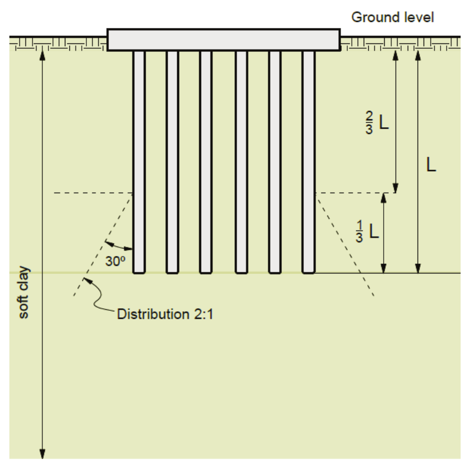
Figure 1.
Solution for a group of piles (Tomlinson & Woodward, 2008).
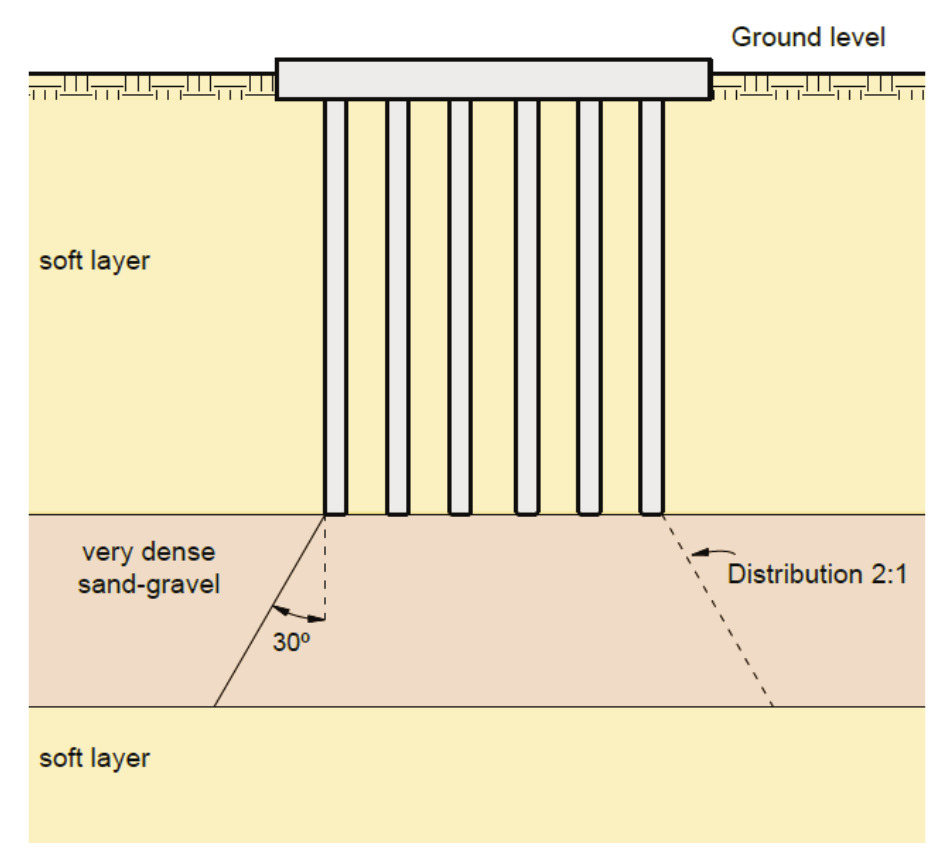
Figure 2.
Solution for a group of piles (Tomlinson & Woodward, 2008).
The flexibility of the foundation is related to its relative stiffness, involving the elastic parameters of the soil and raft, in addition to the geometric characteristics of the raft. In the case of piled rafts, Equation (1) can be used.
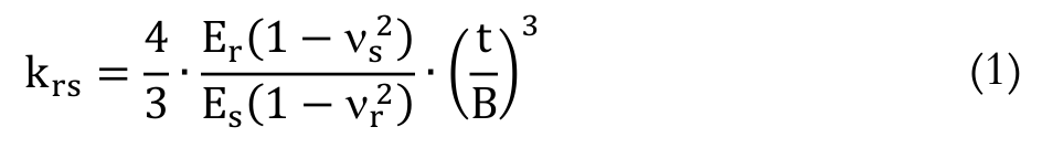 (1)
(1)where Es – soil deformability modulus; Er – raft deformability modulus; s –Poisson's ratio of the soil; r –Poisson’s ratio of the raft; t – thickness of the raft; and B – width of the raft (in plan view).
Bending moment distribution in the piled raft can be affected by changes in the soil-pile stiffness ratio, while the load absorbed by the piles increases with increasing KPS (pile-soil relative stiffness) and Ep/Es. The central pile absorbs a higher load percent in relation to the other piles with lower KPS values, and for higher values, all piles have approximately the same load share (Fattah, Al-Mosawi, & Al-Zayadi, 2014).
According to Viggiani, Mandolini, and Russo (2012), the geometric parameter that best characterizes a group of foundations is related to the settlement rate (R), as shown in Equation (2).
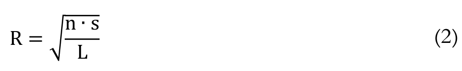 (2)
(2)where n – number of piles; s – spacing between piles; and L – length of the pile.
Thus, the authors suggest that the reduction factor RG can be plotted as a function of R, according to Equation (3).
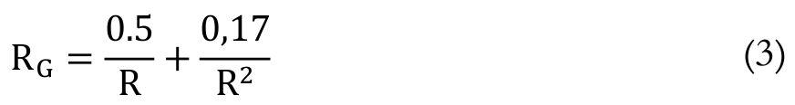 (3)
(3)The settlement for a group of piles can be obtained in accordance with Equation (4).
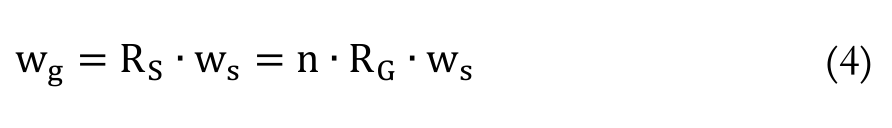 (4)
(4)where n – number of piles; ws – settlement for a single pile; and RS – amplification factor, referred to as the group settlement rate.
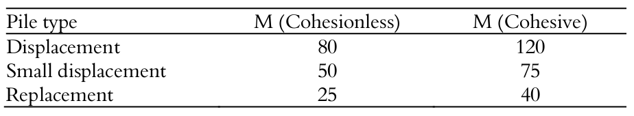
Viggiani and Viggiani (2008) state that the calculation of a single pile settlement can be empirically performed using Equation (5) and the values shown in Table 1.
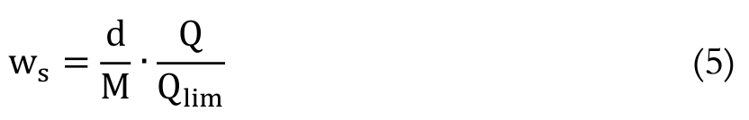 (5)
(5)where d – pile diameter; M – tabulated factor (Table 1); Q – applied load; and Qlim – pile load capacity.
It should be noted that empirically estimated settlement can then be compared to the average settlement obtained by numerical analysis.
Comodromos, Papadopoulou, & Laloui (2016) present in their work a study on the distribution of piles in a raft. The authors comment that the load amplification factor of the piles in the system depends on the configuration and load magnitude. They also found that the ratio of the group settlement to the individual pile settlement reaches its maximum value for small loads and displacements. When the pile load increases, the interaction effect decreases regardless of group configuration.
According to Lee, Park, and Park (2015), when the spacing between piles increases, the proportion of load on the piles becomes higher and pile-pile interaction decreases. In situations with large spacing between piles, the contribution of the raft to the load capacity can be disregarded; in this case, only the piles are considered.
Piles under the raft must be properly located so that the settlement between them is as close as possible. This is made possible by adopting the same stiffness. Accordingly, not only settlement in the area of the plates but also the intensity of internal stresses will be uniform (Urbonas, Sližytė, & Mackevičius, 2016).
A raft’s relative stiffness (thickness) has an important effect on the differential settlements but has a negligible effect on the average settlement and load distribution between piles and the raft (El-Garhy, Galil, Youssef, & Raia, 2013).
Several studies have been conducted to assess the load distribution between piles and a raft. Recent studies propose new and advanced forms of approach. De Sanctis & Russo, 2008 studied the relationship of the percentage of the total applied load with respect to the area of rafts and piles according to the number of piles in the system. The authors comment that the raft contribution can be significant and in some cases greater than 40%.
Materials and methods
To develop this study, piled rafts composed of 9, 16 and 25 piles were analyzed. The piles were 0.3 m in diameter (d) and 7 m in length (L) and were supported on soil under rafts with varying thicknesses of 0.5, 1.0 and 2.0 m. Figure 3 shows the dimensions of the piled rafts, the piles’ distribution and spacing, the raft thicknesses and the diameter of the piles. The subsoil was simulated using an isotropic and homogeneous soil with a deformability modulus constant with depth.
The piled raft was subjected to 300 kPa of uniformly distributed load, simulating a small- to medium-sized building on the surface. The numerical modeling performed in this study was constructed from ¼ of the problem in question due to the symmetry along the axis of the piles and raft, resulting in a rectangular block with a 20-m x 20-m cross section whose depth was a function of the length of the piles (Figure 4).
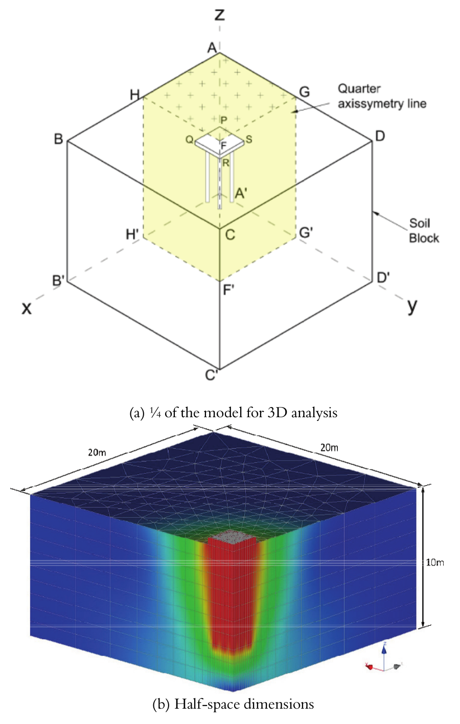
Figure 3.
Piled rafts studied.
These dimensions were assigned on the basis of tests performed to ensure that boundary conditions conferred on the ends of the problems could be regarded as non-displaceable or possessing very low displacements and could thus not exert any influence on the result of the analysis. The variation of the thickness and the amount of piles in the piled raft made it possible to evaluate the influence of the relative stiffness of the foundation.
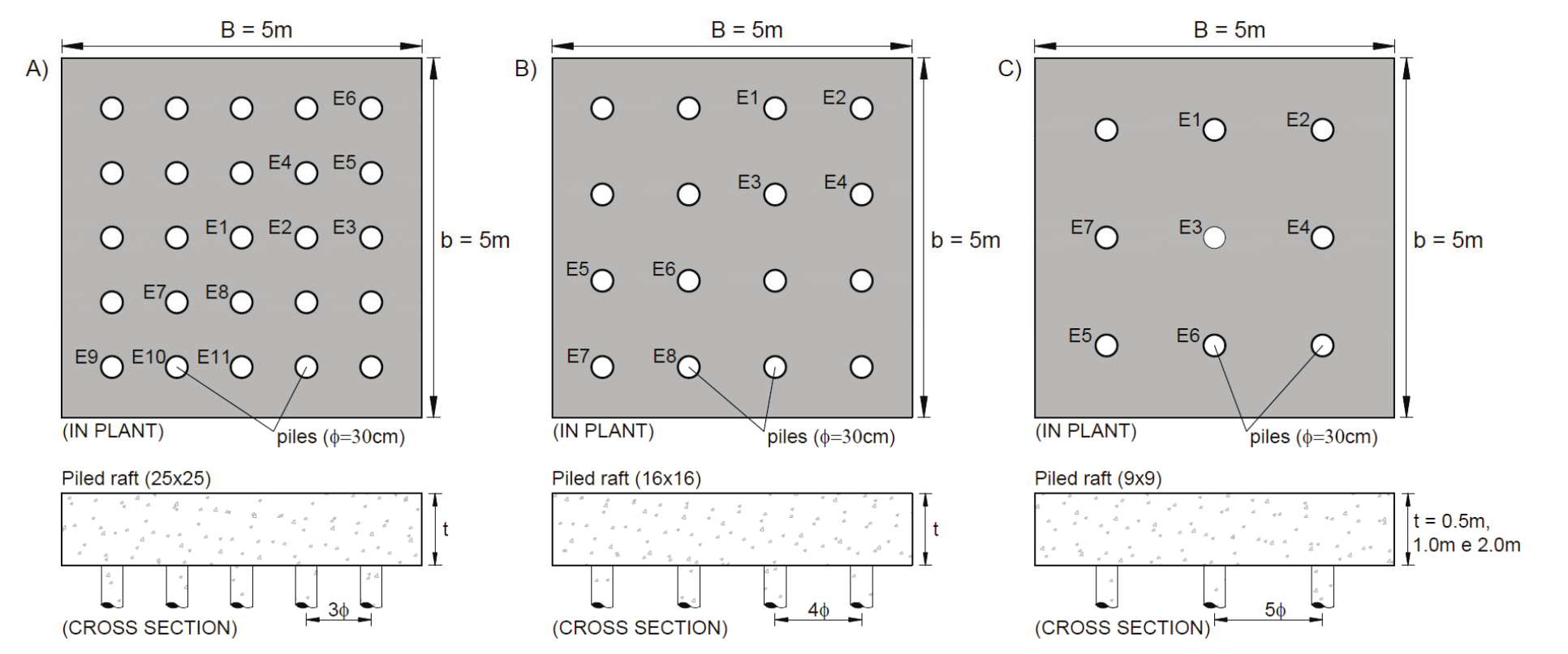
Figure 4.
Numerical model.
A traditional, theoretical, elasto-plastic Mohr Coulomb model was used with a finite element mesh composed by triangular elements with quadratic interpolation. The elements were extruded at every meter in depth in order to render the 3D aspect of the problem. CESAR-LCPC® v.5 software was used in the numerical analyses presented here. Soil properties assigned to the different soil layers followed adopted failure criteria and are given by the following parameters compiled in Table 2: specific weight (); cohesion (c); angle of friction ( ); elasticity modulus (E) and Poisson’s coefficient (). A parabolic model, valid for elements with a brittle-type behavior, was assigned to the pile’s structural element, i.e., the concrete, thus with values related to their compressive resistance (Rc), tensile strength (Rt), specific gravity and elastic parameters, such as, elasticity modulus and the Poisson's coefficient.
The parameters used in the numerical analysis of the soil and structural element are shown in Table 2. These are average parameters adopted for the purpose of a qualitative assessment and are not intended to analyze a specific soil.
Results and discussions
At the end of the numerical analyses, points of interest were delimitated, i.e., the axis of the piles, from top to tip, to determine settlement and loads. Table 3 shows the values of the ratio between the load in a particular pile and the average load on piles and their respective stiffnesses as calculated with Equation (1) (for the three analyzed piled rafts).
The variation of the total load absorbed as a function of the amount of piles and thickness of the raft are shown in Figure 5. It is noted that the load absorbed by the piled rafts is dissipated as a function of the number of piles, an effect that is observed primarily for the settings of the 9 (3x3) and 16 (4x4) pile groups. The increased stiffness of the raft is shown to reduce the average load on the top of the piles. Such behavior is primarily observed in the set of 9 piles. In the case of the piled raft composed of 25 piles, the load remains virtually unchanged for different thicknesses of the raft.
The loads absorbed by the piles in relation to those absorbed by the raft-soil contact, for the three types of rafts analyzed, in terms of the number of piles and raft thicknesses are presented in Figure 6. Analyzing the piled raft composed of 9 piles (3x3) revealed that with the increasing raft-soil relative stiffness (Krs) obtained by increasing the thickness to 1.0 m, a greater share of the piles was reached. Analogous behavior was obtained for all piled rafts analyzed for the 1.0 m thickness, revealing a more effective contribution of the piles with an equivalent stiffness. However, increasing the thickness of the raft from 1.0 to 2.0 m changed the system behavior, causing the piles to return to the load level when the thickness was 0.5 m.
Figure 5 also shows that for the raft that is 1.0 m thick, an increase in the amount of piles from 9 to 16 and then to 25 resulted in a smaller percent load share from 81 to 74% and then 67%, respectively.
Yet another analysis was performed with respect to the positioning of the piles over the raft. From the results obtained in the modeling exercise, it was possible to individually analyze the piles given their location in the group (center, corner and side). Figure 7 shows the distribution of loads on the piles placed in the center of the raft, the distribution in which the central piles exhibited a decrease in percent share in relation to the average load on the piles (Q/Qav). In other words, for the piled rafts composed of 16 and 25 piles, increasing Krs as a consequence of increasing the amount of piles and thickness of the raft caused a reduction in the involvement of central piles. An opposite effect occurred with the piles located at the corner of the piled rafts, which exhibited increased participation in load capacity (Q/Qav) with increasing relative stiffness from 1.5 to 10.7 and 77.9 (Figure 8). In this context, it appears that there is a tendency for the applied load to be redistributed among piles as the relative stiffness increases (from the central piles to those at the corners), as, in the side piles, the ratio Q/Qav remained virtually unchanged for all piled rafts due to their increase in thickness (Figure 9).

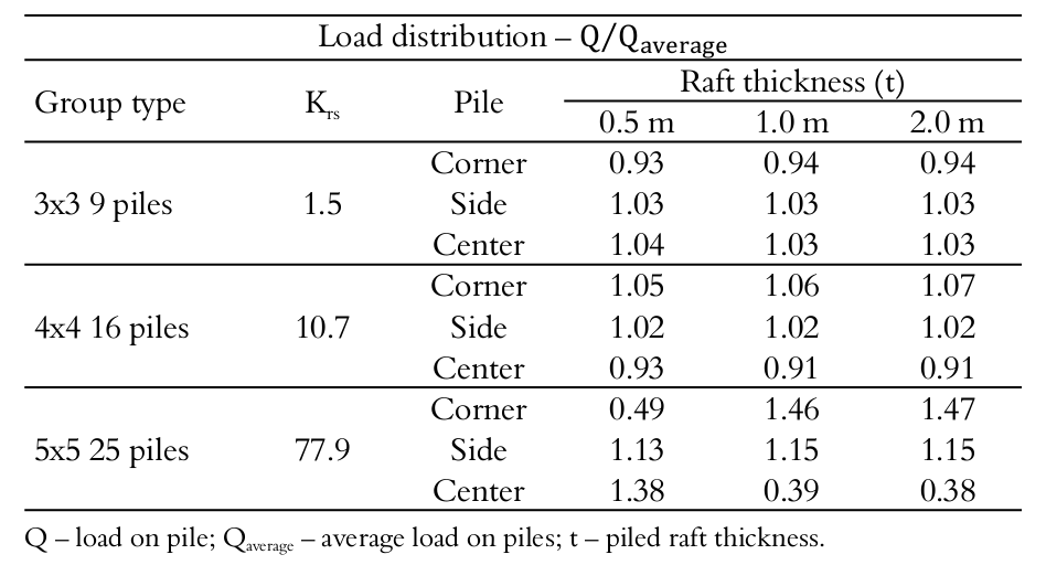
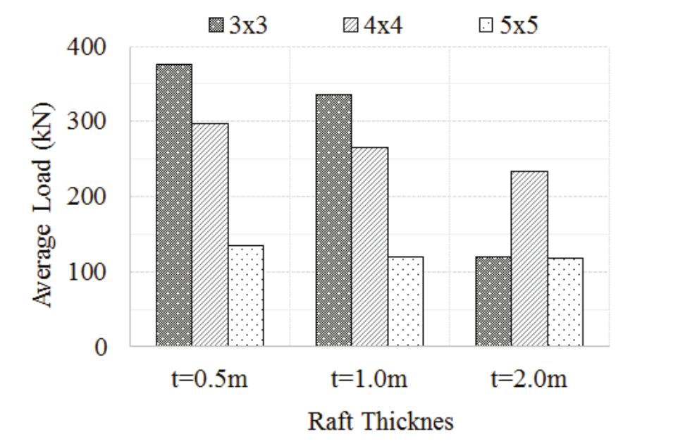
Figure 5.
Average load applied to the top of the piled raft piles.
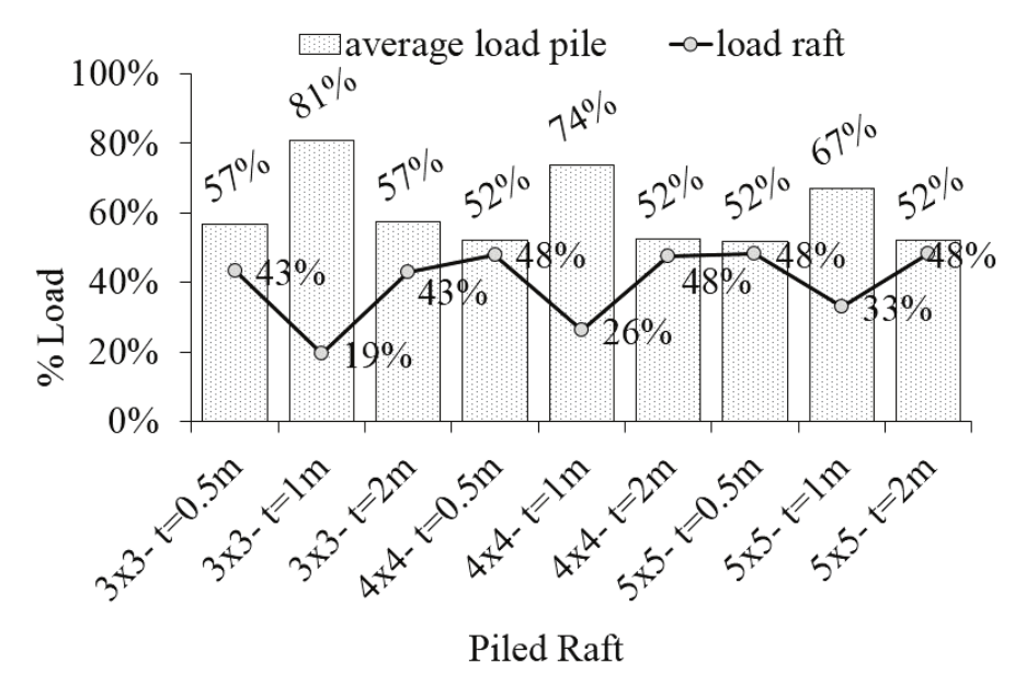
Figure 6.
Average load absorbed by the piles and raft-soil contact.
However, it appears that for the piled raft composed of 9 piles (3x3), the load on the central pile decreases when the value of Krs increases from 1.5 to 10.7 then rises sharply (Figure 7). The corner piles had moderately increased participation in the load capacity with Krs increasing from 1.5 to 10.7. However, the load capacity markedly decreases when Krs was increased to 77.9, as shown in Figure 8.
Figure 9 shows that the side piles tend to suffer no significant influence of the variation of the relative stiffness (Krs). The load obtained for these piles showed little increase in the participation in load capacity of the piles, and only for higher values of Krs.
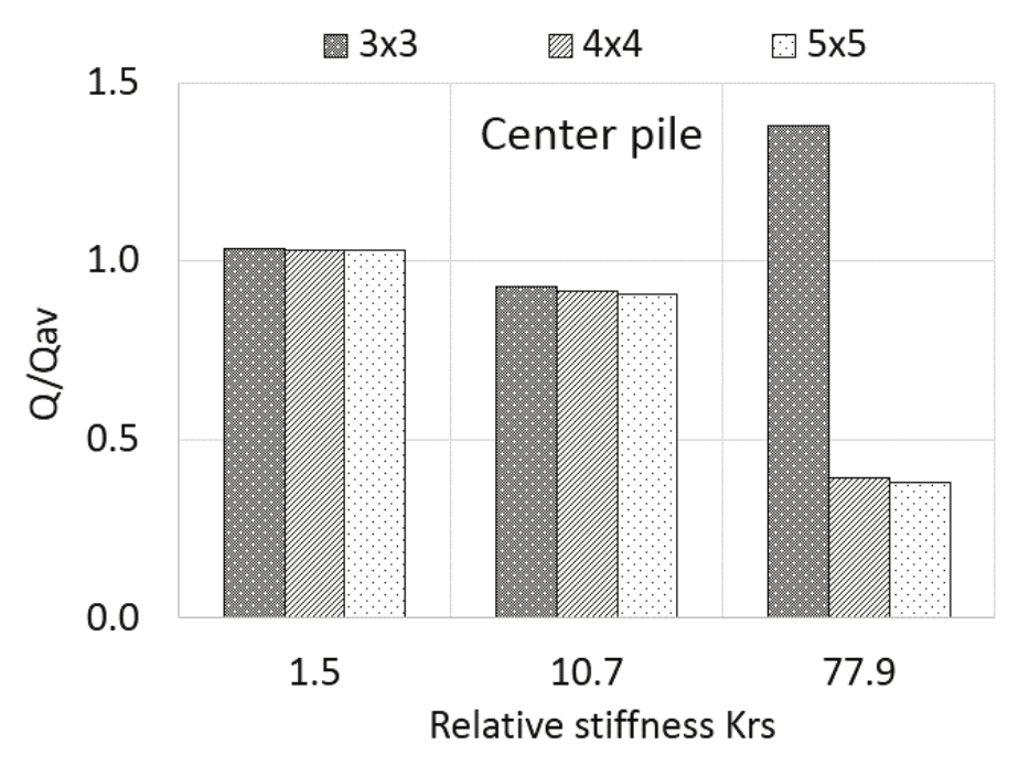
Figure 7.
Load absorbed by the central piles.
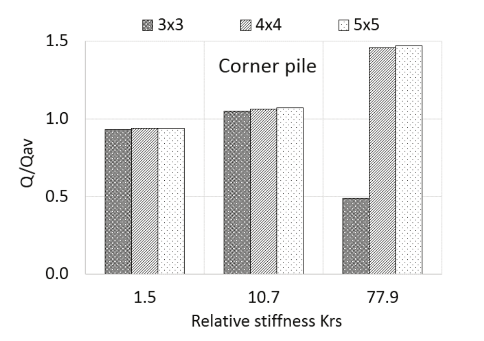
Figure 8.
Load absorbed by the corner piles.
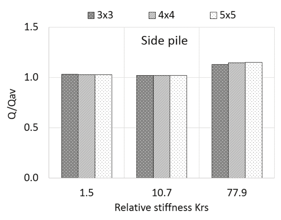
Figure 9.
Load absorbed by the side piles.
It can be observed in Figure 10 that for piled rafts with 9 piles, the central piles had a decreased share in the load absorption as a function of the increased raft thickness, especially in the range from 0.5 to 2.0 m. The reverse situation was observed for the corner piles, wherein a significant reduction is noted in the Q/Qav ratio participation in relation to the increased thickness of the raft. The performance of the side piles (positioned at the average height on the side of the raft) was virtually unchanged by increasing the thickness of the raft. In these situations, compared to one another, the net contact area was kept constant, as was the number of piles. That is, the variable in this case was limited to determine the effect of the load absorption by the piles as a function of increasing thickness (t) of the piled raft.
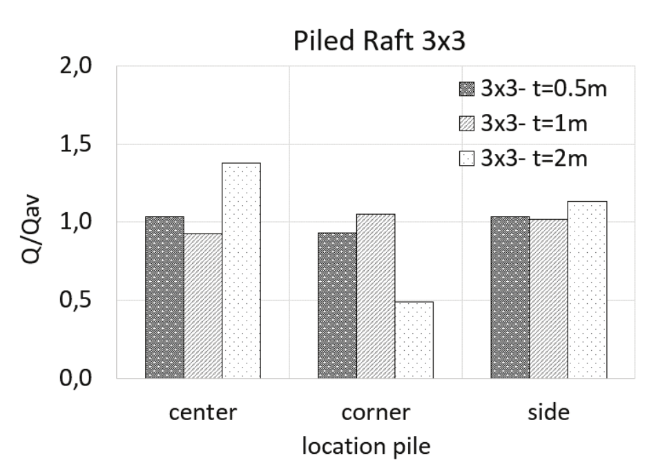
Figure 10.
Load distribution on the piles of the 9-pile (3x3) piled raft.
Figures 11 and 12 show that the central piles of the piled rafts composed of 16 and 25 piles had decreased Q/Qav ratios due to the increased thicknesses of the rafts. These figures also show that for corner piles, the Q/Qav ratio increased due to the increased thickness of the raft. The side piles do not present any significant variation due to the variation in raft thickness.
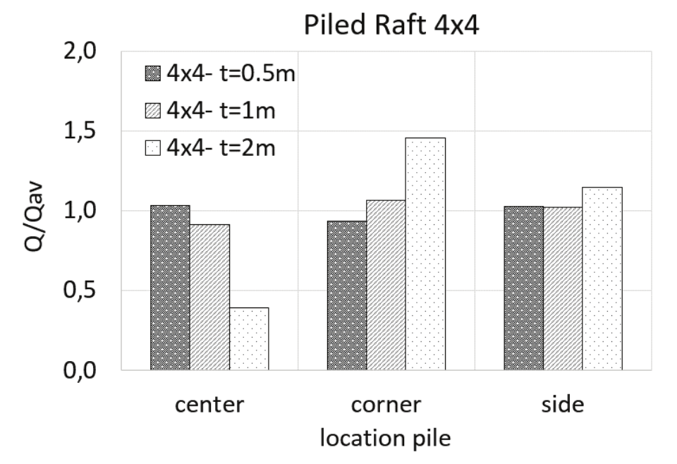
Figure 11.
Load distribution on the piles of the 16-pile (4x4) piled raft.
The thickness and number of piles of the rafts also influenced the load distribution between the side friction and tip strength, as shown in Figure 13. In the case of the raft with nine (9) piles, increasing the piled raft thickness resulted in reduced lateral friction, accompanied by a significant increase in tip strength participation. This effect occurred when the raft thickness increased from t = 1 to 2 m (Figure 13). Note that piled rafts with larger spacing between piles are more sensitive to increases in thickness. That is, with an increase in relative stiffness, a load distribution occurs that tends to be more uniformly distributed in the raft-soil contact and can subsequently influence the skin friction in the first few meters of the pile length.
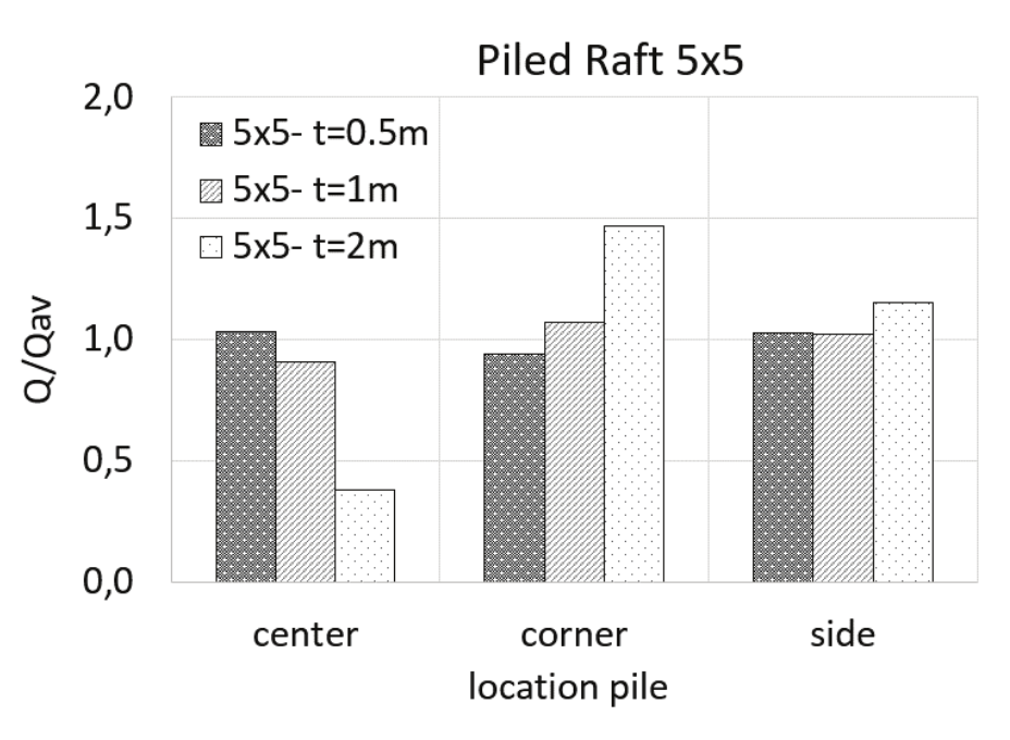
Figure 12.
Load distribution on the piles of the 25-pile (5x5) piled raft.
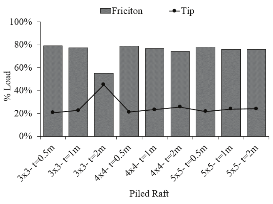
Figure 13.
Portion of side and tip friction in relation to the load supported by the pile.
The observed settlements varied depending on the intensity of the applied loads (Figure 14). It was found that the Q/Qmax curves, as a function of the settlement percentage in relation to the pile diameter, presented intense mobilization for the settlement, equivalent to 5% of a pile’s diameter. In turn, the Q/Qmax ratio for this settlement is approximately 2.0. Settlement then tends asymptotically to a Q/Qmax ratio on the order of 1.0. Comparing the settlement intensity obtained through numerical analysis to the results obtained from the analytical method presented, for the piled rafts composed of 9 piles (3x3), the results presented good agreement for all the studied raft thicknesses (Figure 15). For the piled rafts composed of 16 and 25 piles, the methods present significant differences for settlement estimates.
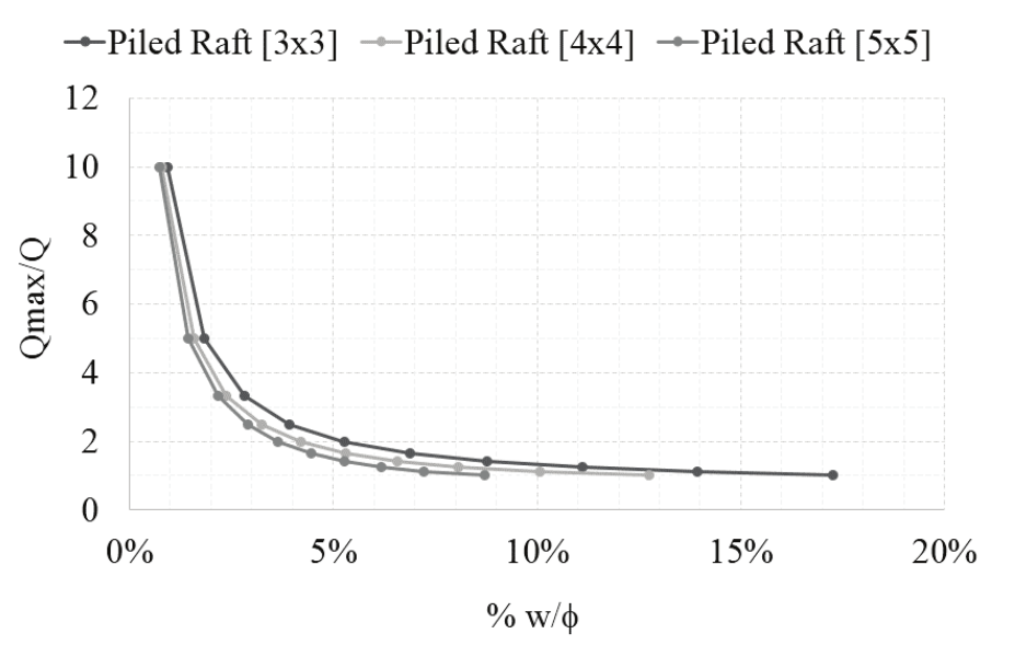
Figure 14.
Variation of Qmax/Q as a function of the w/f ratio.
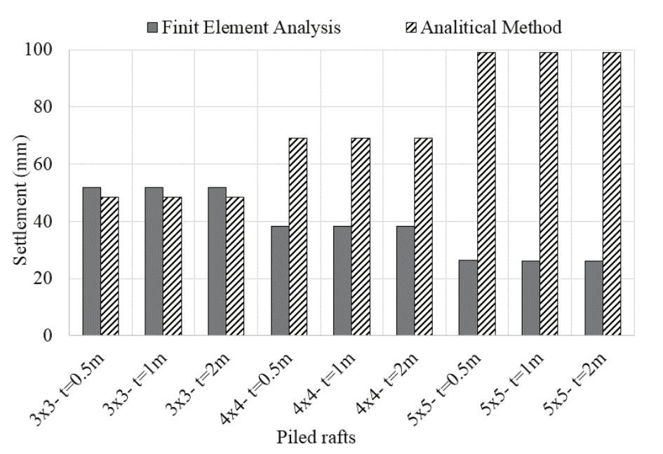
Figure 15.
Comparison of results from numerical analysis and analytical methods.
For all the examined cases, Figure 15 shows that the numerical analysis presented an average settlement of approximately 40 mm, whereas the results of the analytical method returned a value on the order of 65 mm. With an increase in the number of piles, it is clear that for the raft consisting of 25 piles, the estimates showed greater divergence such that the analytical method overestimated settlements with values on the order of 99 mm in comparison to 25 mm from the numerical model.
The differences in the estimated settlement between the numerical model and the analytical model may be related to how each estimates settlement and to the parameters that each considers, especially with regard to the net contact area and/or to the spacing between piles.
The analytical method used to estimate the settlement in piled foundations should consider the arrangement, amount and geometry (length and diameter) of the piles, conducting the choice of the appropriate method (equivalent column or raft equivalent).
Conclusion
The settlement estimate in piled rafts should consider the relative stiffness with regard to the number of piles, net contact area and thus the spacing adopted between piles.
On average, 80% of the load applied on top of the piles was absorbed by skin friction and 20% by tip load.
The contribution of the piles to the piled raft load capacity varies according to their position and to the thickness of the piled raft. Rafts with spacing between piles  (3x3 - 9 piles) mobilized greater load participation in central piles with the increased thickness of the raft. In turn, this share decreased in piled rafts that were 4x4
  and 5x5
  .
.
Rafts with spacing between piles  (3x3, 9 piles) exhibited a load share decrease on the corner piles with increasing thickness of the raft. Conversely, this contribution increased in piled rafts that were 4x4
  and 5x5
  .
.
Piled rafts with spacing larger than three times the diameter of the pile  , which had consequently more net contact area, were less influenced, in terms of load capacity and settlement, by an increase in the relative stiffness via an increase in raft thickness.
Changing the relative stiffness of piled rafts by changing their thickness influenced how the mobilization of the strength of the piles occurred upon loading the raft. Accordingly, for rafts with high values of Krs, the tip strength increases significantly, although the skin frictional strength still remains superior in relation to the strength of the pile.
Acknowledgements
The authors wish to thank the Sao Paulo Research Foundation (Fundação de Amparo à Pesquisa de São Paulo – FAPESP) and the University of Campinas (Unicamp).
References
Abbas, J. M., Chik, Z. H., & Taha, M. R. (2008). Effect of pile cap system on the distribution of bending moment of cap. ARPN Journal of Engineering and Applied Sciences, 3(4), 46-50.
Babanov, V. V., & Shashkin, V. A. (2012). Design analysis of the functioning of pile foundations with low and high rafts and consideration of nonlinear bed performance. Soil Mechanics and Foundation Engineering, 49(2), 43-49. doi: 10.1007/s11204-012-9165-9
Basile, F. (2015). Non-linear analysis of vertically loaded piled rafts. Computers and Geotechnics, 63(1), 73-82. doi: 10.1016/j.compgeo.2014.08.011
Bourgeois, E., de Buhan, P., & Hassen, G. (2012). Settlement analysis of piled-raft foundations by means of a multiphase model accounting for soil-pile interactions. Computers and Geotechnics, 46(1), 26-38. doi: 10.1016/j.compgeo.2012.05.015
Cho, J., Lee, J.-H., Jeong, S., & Lee, J. (2012). The settlement behavior of piled raft in clay soils. Ocean Engineering, 53, 153-163. doi: 10.1016/j.oceaneng.2012.06.003
Comodromos, E. M., Papadopoulou, M. C., & Laloui, L. (2016). Contribution to the design methodologies of piled raft foundations under combined loadings. Canadian Geotechnical Journal, 53(4), 559-577. doi: 10.1139/cgj-2015-0251
Comodromos, E. M., Papadopoulou, M. C., & Rentzeperis, I. K. (2009). Pile foundation analysis and design using experimental data and 3-D numerical analysis. Computers and Geotechnics, 36(5), 819-836. doi: 10.1016/j.compgeo.2009.01.011
de Sanctis, L., & Russo, G. (2008). Analysis and Performance of Piled Rafts Designed Using Innovative Criteria. Journal of Geotechnical and Geoenvironmental Engineering, 134(8), 1118-1128. doi: 10.1061/(ASCE)1090-0241(2008)134:8(1118)
El-Garhy, B., Galil, A. A., Youssef, A.-F., & Raia, M. A. (2013). Behavior of raft on settlement reducing piles: Experimental model study. Journal of Rock Mechanics and Geotechnical Engineering, 5(5), 389-399. doi: 10.1016/j.jrmge.2013.07.005
Fattah, M. Y., Al-Mosawi, M. J., & Al-Zayadi, A. A. O. (2014). International Journal of Civil Engineering and Technology (IJCIET). International Journal of Civil Engineering and Technology, 5(7), 130-148.
Katzenbach, R., & Choudhury, D. (2013). Combined Pile-Raft Foundation Guideline. (R. Katzenbach, Ed.) (1st ed.). Darmstadt: Institute and Laboratory of Geotechnics.
Lee, J., Kim, Y., & Jeong, S. (2010). Three-dimensional analysis of bearing behavior of piled raft on soft clay. Computers and Geotechnics, 37(1-2), 103-114. doi: 10.1016/j.compgeo.2009.07.009
Lee, J., Park, D., Park, D., & Park, K. (2015). Estimation of load-sharing ratios for piled rafts in sands that includes interaction effects. Computers and Geotechnics, 63, 306-314. doi: 10.1016/j.compgeo.2014.10.014
Poulos, H. G. (2011). The De Mello Foundation Engineering Legacy. Soils and Rocks, 34(1), 3-34.
Rabiei, M., & Choobbasti, A. J. (2016). Piled Raft Design Strategies for High Rise Buildings. Geotechnical and Geological Engineering, 34(1), 75-85. doi: 10.10 07/s10706-015-9929-x
Soares, W. C., Coutinho, R. Q., & Pinto da Cunha, R. (2015). Piled raft with hollow auger piles founded in a Brazilian granular deposit. Canadian Geotechnical Journal, 52(8), 1005-1022. doi: 10.1139/cgj-2014-0087
Taghavi Ghalesari, A., Barari, A., Fardad Amini, P., & Ibsen, L. B. (2015). Development of optimum design from static response of pile-raft interaction. Journal of Marine Science and Technology, 20(2), 331-343. doi: 10.1007/s00773-014-0286-x
Tang, Y. J., Pei, J., & Zhao, X. H. (2014). Design and measurement of piled-raft foundations. Proceedings of the Institution of Civil Engineers - Geotechnical Engineering, 167(5), 461-475. doi: 10.1680/geng.13.00004
Tomlinson, M., & Woodward, J. (2008). Pile design and construction practice (5th ed.). London and New York: Taylor & Francis Group.
Urbonas, K., Sližytė, D., & Mackevičius, R. (2016). Influence of the pile stiffness on the ground slab behaviour. Journal of Civil Engineering and Management, 22(5), 690-698. doi: 10.3846/13923730.2016.1176597
Viggiani, C., Mandolini, A., & Russo, G. (2012). Piles and Pile Groups. In Applied Soil Mechanics (1st ed., p. 286-331). Hoboken, NJ: John Wiley & Sons, Inc. doi: 10.1002/9780470168097.ch8
Viggiani, G., & Viggiani, G. M. B. (2008). Diagnostics for the protection and preservation of materials in the built. In II ruolo dell’osservazione dele opere nell’Ingegneria Geotecnica. San Leucio: Diacomast 2.
Notes
Author notes
jean.garcia@ufu.br