Engenharia Mecânica
Influence of different dielectrics fluids on the surface integrity of high speed steel
Influência de diferentes fluidos dielétricos na integridade superficial do aço-rápido
Influence of different dielectrics fluids on the surface integrity of high speed steel
Acta Scientiarum. Technology, vol. 40, 2018
Universidade Estadual de Maringá

This work is licensed under Creative Commons Attribution 4.0 International.
Received: 13 February 2017
Accepted: 20 September 2017
Abstract: Machining by electrical discharges is a huge process for the machining of complex shapes in materials that are electrical conductors, in particular for those of high hardness, difficult to be machined by conventional processes. Its unique feature of using thermal energy to machine parts has been a distinctive advantage in the manufacture of moulds, dies, aerospace components, and surgical, and of course, it can be widely used in the industry of tooling in the manufacture of geometric features, such as, for example, cavities narrow and deep, grooves, thin-walled, and small corner radii. One of the materials that are widely machined by spark-erosion is the tool steel (ABNT M2, has good toughness, hardness and abrasion resistance being indicated for the manufacture of stamping dies. The present work describes experiments conducted on a modern machine eletroerosiva using the electrode-tool of electrolytic copper in the machining of parts from high-speed steel (ABNT M2 to investigate the effect of different fluid dielectric about the generation of microcracks and heat affected zone (HAZ). A review of the comparative shows that the surfaces machined with dielectric fluid “A” have low values in the length of the microcracks compared with the other fluids. In the meantime, the machined surfaces with the dielectric “B” have a lower density of microcracks.
Keywords: machining by electrical discharges, dielectric fluid, microcracks and heat affected zone.
Resumo: A usinagem por descargas elétricas é um processo extraordinário para usinagem de formas complexas em materiais condutores elétricos, sobretudo para aqueles de elevada dureza, difíceis de serem usinados por processos convencionais. Sua característica única de empregar a energia térmica para usinar peças tem sido uma vantagem distintiva na confecção de moldes, matrizes, componentes aeroespaciais e cirúrgicos, além é claro, de ser amplamente utilizado na indústria de ferramentaria na confecção de características geométricas, como, por exemplo, cavidades estreitas e profundas, ranhuras de paredes finas, e pequenos raios de canto. Um dos materiais que são largamente usinados por eletroerosão é o aço-ferramenta ABNT M2, que apresenta boa tenacidade, dureza e resistência a abrasão sendo indicado para fabricação de matrizes de estampagem. O presente trabalho descreve experimentos realizados em uma moderna máquina eletroerosiva usando eletrodo-ferramenta de cobre eletrolítico na usinagem de peças de aço rápido ABNT M2 visando investigar o efeito de diferentes fluidos dielétricos sobre a geração de microtrincas e zona afetada pelo calor (ZAC). Uma análise comparativa comprova que as superfícies usinadas com fluido dielétrico “A” possuem baixos valores no comprimento das microtrincas comparado com os demais fluidos. Entretanto as superfícies usinadas com o dielétrico “B” possuem baixa densidade de microtrincas.
Palavras-chave: usinagem por descargas elétricas, fluido dielétrico, microtrincas e zona afetada pelo calor.
Introduction
Joseph Priestley, an English chemist, was the first to discover, in 1766, the erosive effect of electric discharges. After discharging a battery, a crater generated by the melting of the material on the cathode surface was observed (Ming & Fuzhu, 2009). Electro-erosion is a process that allows the machining of holes, grooves and surfaces, in more complex forms, in conductive materials, especially those that have high hardness that could not be manufactured by traditional machining processes (Izquierdo, Sánchez, Plaza, Pombo, & Ortega, 2009; Shuyang, Yumei, & Yan, 2011).
According to Mahardika, Tsujimoto, and Mitsui (2008), in the machining of any component one must keep in mind that there are two factors that are defined and controlled. The first one is related to the geometric irregularities of the surface and is denominated superficial texture, and the second, with the metallurgical alterations of the superficial and underground layer, denominated superficial integrity. In the processing of some products, these two aspects must be defined, measured and maintained within the specified limits.
According to Manjaiah, Narendranath, Basavarajappa and Gaitonde (2015), there is a questioning regarding the electrical discharge machining (EDM) process, regarding the texture and surface integrity of the machined parts. Further machining processes are recommended for the removal of poor surface layers in mechanical properties such as electrochemical machining (ECM) or even traditional machining processes such as polishing.
Mahardika et al. (2008) cite that the main causes of superficial changes produced by the electro-erosion machining process are: high temperatures generated in the process; chemical reactions; excessive electrical current and energy density during machining.
During each electrical discharge, high temperatures are generated, causing local melting or even evaporation of the material to be machined. At each discharge, a crater is formed in the material and a small crater is formed in the electrode. Of all the molten material produced in each discharge, only 15%, or less, are withdrawn by the dielectric liquid. The remainder of the molten material solidifies to form a rough surface. The characteristics of the surface obtained, overlapping of craters, impurities globules, chimneys, bubbles (formed when the trapped gases are released by the resolidified material), are revealed by scanning electron microscopy (Guo, Di & Wei, 2016; Minh, Mustafizur & Yoke, 2013; Amandeep & Ragot, 2015).
The surface integrity of the part is compromised after the process, as it is attacked by ions and or electrons that promote the removal of the material by means of random explosions. There is no defined pattern of the amount of material removed. It is only known that greater current intensity in long periods and larger work gaps produces more intense explosions, consequently, a greater removal of material, promoting a coarser texture (Henriques, Peças, & Silva, 2014). In addition, a layer called a white zone is formed, located on the surface of the workpiece and another one called the heat-affected zone, which is located just below the white zone between it and the substrate of the part (Lenan, Jianyi, Xiaoshun, Zhiliang & Jingyu, 2015). It also occurs the appearance of microcracks and pores on the surface of the eroded part, besides the adhesion of eroded particles on the surface of the same (Okunkova, Peretyagin, Seleznyov, Fedorov, & Kozochkin, 2016). The main objective of this research is to study the effect of different dielectric fluids, about the generation of microcracks and Heat Affected Zone (HAZ) during the electro-erosion machining of the high speed steel ABNT M2 under thinning regime. The choice of this material is due to the fact that it is widely used as a cutting tool, and its application is not only greater because of its low machinability through traditional machining processes.
Experimental procedures
The experimental phase of this work was performed in an EDM machine Engemaq 440NC. It consists mainly of a compartment for circulation of the dielectric fluid, a hydraulic compartment for drive of the head, the mechanical unit itself, where the servomechanism is located to maintain the constant gap and the source of rectified current. The sample and the tool electrode were immersed in the dielectric oil inside the tanks of the EDM machine.
Due to this work being developed with the application of copper electrode during the process of machining by electric discharges, some specific characteristics of the fast steel bits are mentioned in Table (1), which will be very important to understanding this work. The side and front views of the ABNT M2 high speed steel part are shown in Figure (1).
Also was used quick steel part ABNT M2 of the tool master brand (called "Bits") with the following chemical composition: 0.85% Carbon; 4.30% Chromium; 1.90% Vanadium; 6.40% Tungsten and 5.00% Molybdenum and, according to the manufacturer, its hardness varies from 64 to 66 HRc. However, tests performed on 27 samples, in a total of 25 measurements, have an average hardness of 60 HRc with a standard deviation of 4.0 points. The choice of this material is due to the fact that its widely used in the manufacturing of tools, and mainly because it is considered a material of difficult machining by conventional machining processes.

The material used was purchased in the shape of the "square" cross section of 9,525 mm side section bars and a length of 127 mm. As regarding of origin, the material used was manufactured by the supplier Avibas and benefited by Tool Master Metallurgical Industry Ltda.
The reason for the fabrication of the tool-electrode geometry shown in Figure (2) is directly related to the removal of eroded residues from the tool-part interface. Injection of the dielectric inside the electrode, associated with the machine's ultra-fast forward and reverse mechanism, allows obtaining adequate cleaning conditions, which are essential to obtain better results during the machining of the bits, besides maintaining the physical and chemical characteristics of it. Another important statement is that the taper at the end of the electrode allows the residues from the machining to pass laterally through the working zone between the electrode and the workpiece.
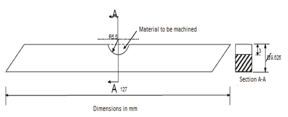
Figure 1.
Configuration of machined part geometry (ABNT M2 high speed steel).
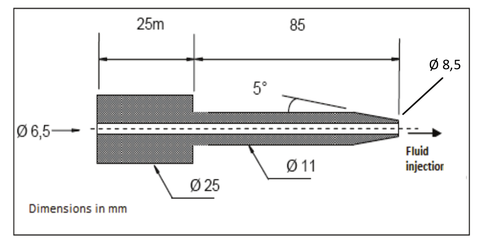
Figure 2.
Schematic representation of the copper electrode tool.
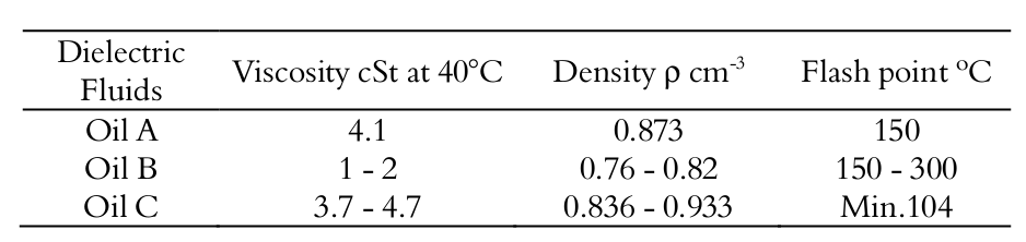
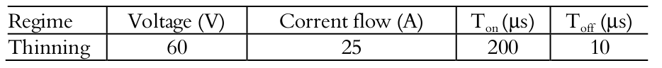
For the established regime, it is theoretically expected that different qualities of dielectric fluids will promote differentiated yields in surface finish and material removal rate. The final parameters that have yielded good results in preliminary tests, were applied to the definitive tests which can be cited: flow = 76.92 mL s-1, volume of dielectric = 36 L, in addition to being used three hydrocarbon oils of industrial origin cited in all text as oils A, B (kerosene) and C, identified in the list of symbols and their characteristics in Table (2). The EDM machine manual ENGEMAQ 440NC was used to determine the most suitable variables for the cutting condition: 60 V voltage, 25 A current, Ton = 200 μs and Toff = 10 μs.
The cutting conditions adopted for the roughing regime, in the machining of ABNT M2 quick steel parts with electrolytic copper electrode tool, can be seen in Table (3).
To perform this analysis, the 5 (five) machined samples (ABNT M2 high speed steel bars) were embedded in bakelite to be sanded and then polished. Sanding grit sizes from 220 to 1000 mesh was used in grinding. For the polishing, diamond paste of 3 and 0.25 μm was used. Then the samples were attacked with a solution containing 50 of 2% Nital and 50% Vilela. This solution is commonly referred to as Nigreen (serves to evidence the presence of layers in the machined region).
The two side sections of each sample were not subjected to chemical attack, in order to facilitate the measurement of the length and density of microcracks in the machined regions, using the Optical Microscope of the brand CARL ZEISS JENA and model Neophot 21 with a Scale which allowed to measure the length of microcracks and at the same time to quantify them.
The evaluations of how the said microcracks behaved along the layers and sublayers produced in the bits immediately after the electro-erosion machining were done using micrographs extracted from the Scanning Electron Microscope (SEM) ZEISS and Optical Microscope NEOPHOT21, and the Microscope Optical of the brand CARL ZEISS JENA was used to analyze the extent and population of microcracks. After values were collected, they were calculated from the amount of microcracks per length of the machined region.
Results and discussion
Figures 3 (a) to 3 (c) show how microcracks propagate on the surface. It is possible to observe that the microcracks are not limited to the layer of molten material, it’s also extending in some cases reaching the base material. In addition to vertical cracks, there are a presence of subsurface cracks, located both inside the recast layer and inside the base material [ex: Fig. 3 (a) and 3 (b)]) is noted. Sub-surface microcracks are usually associated with traction cracks (vertical). Another aspect to be noted is that vertical cracks are often associated with defects such as bubbles or voids (ex: Fig. 3 (a), 3 (b)).
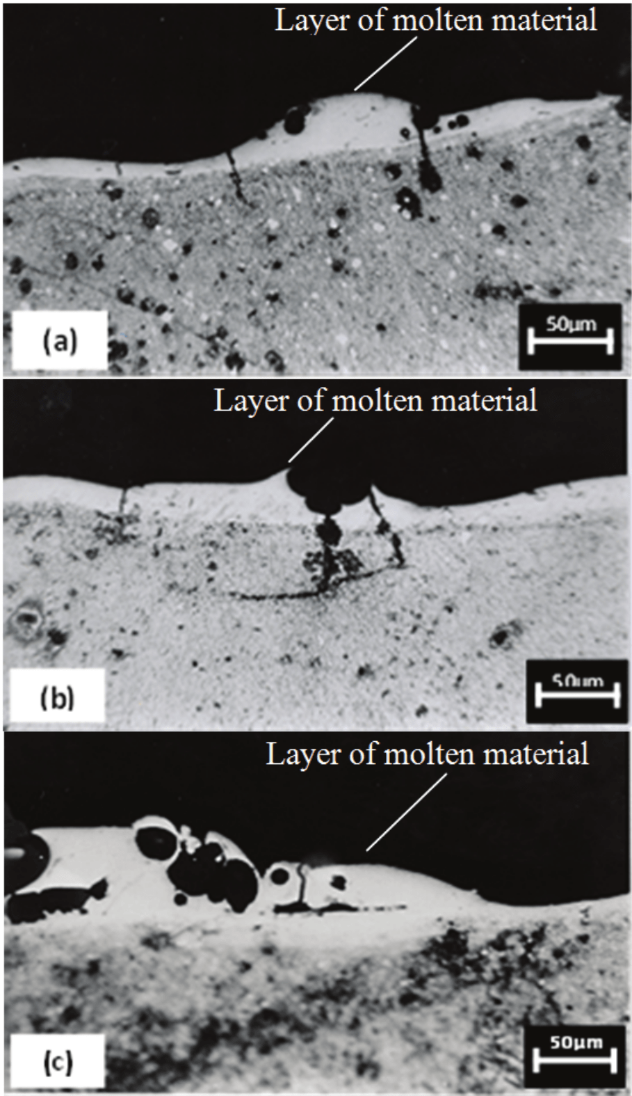
Figure 3.
Side view obtained by optical microscopy of the machined surface of ABNT M2 high speed steel: (a) Dielectric fluid A; (b) Dielectric fluid B and (c) Dielectric fluid C
The cracks generated during the EDM process in the ABNT M2 high speed steel can still surround the craters and bubbles of the recast and resolidified material. According to Marafona and Arlindo (2009), these microcracks have their depths and extensions determined by the discharge energy. The surfaces shown above are also very similar to those observed by Okunkova (2016). This same author states in his works that the development of microcracks is related to the emergence of high thermal stresses that exceed the maximum tensile strength of the material.
The depths or average lengths of the microcracks observed on the EDM machined surfaces are shown in Figure (4). In Figure (5) we have the density of microcracks on the machined surface.
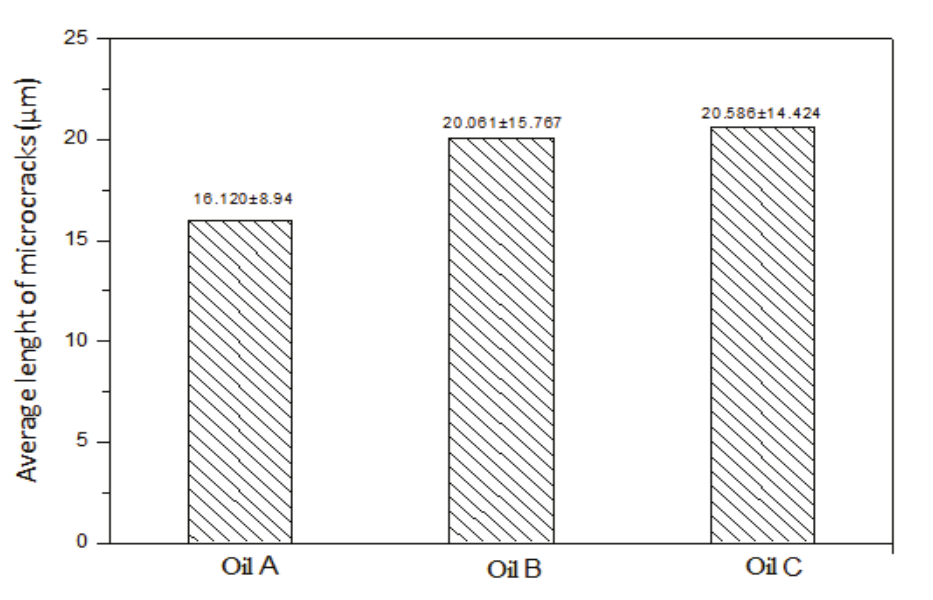
Figure 4.
Average length of the microcracks along the machined surface.
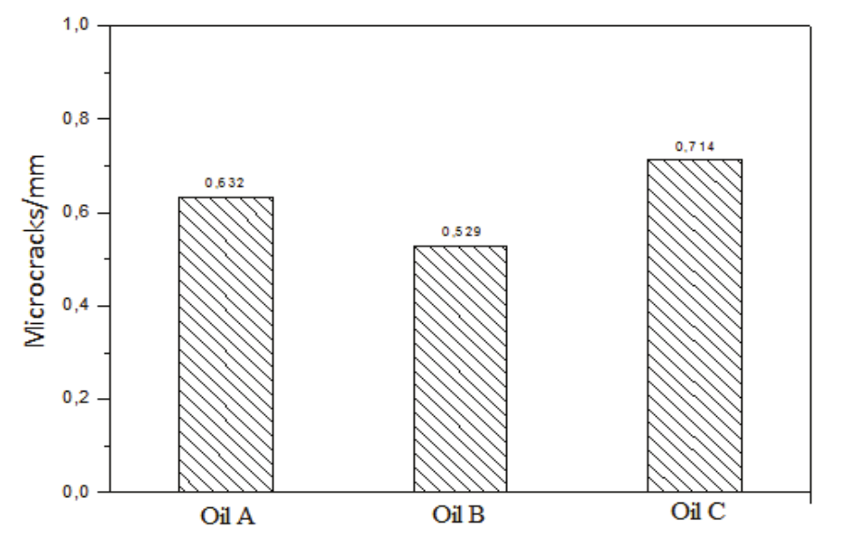
Figure 5.
Amount of microcracks per millimeter of the machined surface.
Figure 4 shows the existence of large standard deviations of crack length in relation to the means values. This can be seen above from Figure 3 (a), where cracks with large differences in size are observed. There is also a tendency to increase the length of the cracks that can be notated when passing from dielectric A to B and C.
Table 4 shows the values of the average height of the layer of molten material and re-deposited on the surface, in addition the average thickness of the heat affected zone.
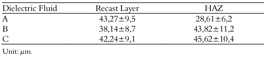
By comparing the graph of Figure 4 and Table 4, it can be seen that in the dielectric fluid machining A, the microcracks are within the heat affected zone. In isolated cases, they were found to cross HAZ, as can be seen in Figure 3 (a).
Furthermore, in the machining with the dielectric B, the microcracks had an average length slightly higher than that verified with the dielectric A. This combined with a smaller thickness of the HAZ in dielectric B led to the formation of a greater amount of cracks that reach the substrate [Figure 3 (b)].
In the machining by electric discharges with dielectric fluid C, a good part of the microcracks were contained in the HAZ. As can be seen from Figure 3 (c).
A detailed analysis on the graph of Figure 4 shows that the samples that were machined with dielectric fluid A present microcracks with an average length around 16,20 μm with a standard deviation of 8.94μm, which is lower when compared to the samples machined with the other dielectric fluids B and C, where these presented an average length of 20,061 and 20,586 μm, respectively.
In the aspect of microcracks, the dielectric fluid A represents an attractive alternative for the machining of ABNT M2 high speed steel.
The dielectric fluid B is more benefited. Analyzing Table (2), which presents some properties of the dielectric fluids used, it can be noted that the B fluid has the lowest viscosity in relation to the A and C fluids. Due to their higher viscosity, they present greater difficulties in the elimination of the products from the erosion by the movement of the same ones in the region of the gap. According to the Arafona and Arlindo (2009), the lower the viscosity the less concentrated discharges, which take away less material from the part. This is reflected in the thickness of the recast layer generated in dielectric fluid B, as shown in Table (4).
Conclusion
The tests carried out with different dielectric fluids in the machining of ABNT M2 high speed steel bars through the EDM process allow the following conclusions:
- On all machined surfaces spherical globules or particles, “chimneys”, craters and cracks resulting from the machining process were observed. Particular attention should be paid to the machined surfaces with the dielectric fluid A as they present lower values of microcrack length when compared to the others, reaching in some cases the base material;
- The samples of ABNT M2 high speed steel machined with dielectric fluid B present lower density of microcracks compared to other dielectric fluids;
- On surfaces machined with dielectric C, a large number of microcracks are contained within the molten material layer, or even in HAZ;
- Because the machined surfaces with dielectric fluid B presented low viscosity values, this is reflected in the small size of the recast layer compared to the other samples machined with dielectrics A and C.
Acknowledgements
The authors are grateful to FAPEMA and FAPEMIG for financial support.
References
Amandeep, S., & Ragot, S. (2015). Effect of Powder Mixed Electric Discharge Machining (PMEDM) on various materials with different powders: A review. International Journal for Innovative Research in Science & Technology, 2(3), 164-169. doi: 10.1515/jmsp-2014-0016
Guo, C., Di, S., & Wei, D. (2016). Study of electrical discharge machining performance in water-based working fluid. Materials and Manufacturing Processes, 31(7), 1865-1871. doi: 10.1080/10426914.2015.1127946
Henriques, E., Peças, P., & Silva, A. (2014). Technology and Manufacturing Process Selection. New York, NY: Springer Verlag. doi: 10.1007/978-1-4471-5544-7
Izquierdo, B., Sánchez, J. A., Plaza S., Pombo I., & Ortega N. (2009). A numerical model of the EDM process considering the effect of multiple discharges. International Journal of Machine Tools and Manufacture, 49(3), 220-229. doi: 10.1016/j.ijmachtools.2008.11.003
Lenan, Z., Jianyi, D., Xiaoshun, Z., Zhiliang, W., & Jingyu, P. (2015). Geometric prediction of conic tool in micro-EDM milling with fix-length compensation using simulation. International Journal of Machine Tools and Manufacture, 89(6), 86-94. doi: 10.1016/j. ijmachtools.2014.11.007
Mahardika, M., Tsujimoto, T., & Mitsui, K. (2008). A new approach on the determination of ease of machining by EDM processes. International Journal of Machine Tools and Manufacture, 48(7), 746-760. doi: 10.1016/j. ijmachtools.2007.12.012
Manjaiah, M., Narendranath, S., Basavarajappa, S., & Gaitonde, V. N. (2015). Effect of electrode material in wire electro discharge machining characteristics of Ti50Ni50−xCux shapememory alloy. Precision Engineering. 41(7), 68-77. doi: 10.1016/j.precisioneng. 2015.01.008
Marafona, J. D., & Arlindo, A. (2009). Influence of workpiece hardness on EDM performance. International Journal of Machine Tools and Manufacture, 49(9), 744-748. doi: 10.1016/j.ijmachtools.2009.03.002
Ming, Z., & Fuzhu, H. (2009). Adaptive control for EDM process with a self-tuning regulator. International Journal of Machine Tools and Manufacture, 49(6), 462-469. doi: 10.1016/j.ijmachtools.2009.01.004
Minh, D. N., Mustafizur, R., & Yoke, S. W. (2013). Modeling of radial gap formed by material dissolution in simultaneous micro-EDM and micro-ECM drilling using deionized water, International Journal of Machine Tools and Manufacture, 66(3), 95-101. doi: 10.10 16/j.ijmachtools.2012.12.001
Okunkova, A., Peretyagin, P., Seleznyov, A., Fedorov, S. V., & Kozochkin, M. (2016). Characterization of material’s defects after electrical discharge machining and research into their technological parameters using vibroacoutstic diagnostics. Advanced Materials Letters, 7(7), 542-548. doi: 10.5185/amlett.2016.6144
Shuyang, L., Yumei, H., & Yan, L. (2011). A plate capacitor model of the EDM process based on the field emission theory. International Journal of Machine Tools and Manufacture, 51(7), 653-659. doi: 10.1016/j.ijmachtools.2011.04.002
Notes
Author notes
jrobert@cct.uema.br