Engenharia Civil
Comparative study of software for road geometric design
Comparative study of software for road geometric design
Acta Scientiarum. Technology, vol. 41, 2019
Universidade Estadual de Maringá
Received: 02 May 2017
Accepted: 01 October 2018
Abstract: This study compared the results obtained in developing a highway geometric design through the use of the softwares TCP-MDT, AutoCADCivil 3D and TopoGRAPH. For this, the results were compared taking into account the technical recommendations of the National Department of Transportation Infrastructure (DNIT). The parameters evaluated were: modeling with contour lines; horizontal layout; vertical layout; superwidth; superelevation; and earth moving calculation. In the digital modeling, small differences were found in the contour, both in the mesh and the final product. There was no difference in the results for the horizontal layout between softwares. For vertical layout, there was a slight difference in the terrain profile possibly caused by the digital modeling of the programs. In superwidth, TopoGRAPH and TCP-MDT were the ones that best met the Brazilian standards. To calculate the superwidth, the best results were found with AutoCADCivil 3D and TCP-MDT. Besides, there were small differences between the respective land volumes computed by the softwares, which may have larger magnitude for a project with greater longitudinal extension. Therefore, it is concluded that the choice of the software can affect since the technical parameters until the planning of the work, with implications on the overall cost.
Keywords: road geometric design, softwares, earthwork.
Introduction
The geometric design of a road has the objective of connecting two or more locations appropriately, that is, observing the conditions of safety and comfort of the users and the technical-economic conditions of the region where the road will pass (Antas, Álvaro, Gonçalo, & Lopes, 2010). In a road, the horizontal and vertical alignments are composed by a set of straight sections (tangents) connected by horizontal and vertical curves, and the cross sections provide valuable information about earth movements volumes in cut and fills (Pontes Filho, 1998; Pimenta & Oliveira, 2004).
For the design of a geometric road, the following elements must be represented: width of tracks; traffic lanes number and shoulder; drainage devices; tangent lengths; ramps; radius of curves; superelevation; superwidth; visibility distance; among others. Its design requires a structured sequence of routines whose purpose is to define the geometric parameters to be adopted for the road according to the design speed and the type of relief (Departamento Nacional de Estradas de Rodagem [Dner], 1999). With this information, it is possible to define the track geometry. Informatics contributes greatly to streamline the road geometric design and facilitate numerous simulations of layout alternatives, quickly and accurately, making possible the evaluation of the geometric design from the point of view of the driver (Han, Middleton, Muzyczka, Minty, & Clayton, 2005, Kühn & Jha, 2006; Kühn & Hendrick, 2010; Kühn, Volker, & Kubik, 2011; Winner, Ancochea, & Graupner, 2012; Figueira, Larocca, Quintanilha, & Kabbach Jr., 2014).
Road geometric designs gain technical quality when executed in specific computer programs. This allows for increased productivity and cost reduction through rapid simulations of different scenarios, minimizing errors and improving the final quality of the project (Van Der Horst & Hogema, 2011; Figueira et al., 2014).
In several computer programs developed for planning roads, three-dimensional visualization technologies have been used, these have contributed not only to the evaluation of the impact of a highway project in the region of its surroundings, but also in the development and study of the elements of the own geometric design (Hassan, Easa, & Halim, 1998; Easa & Dabbour, 2005; Han et al., 2005; Figueira et al., 2014; Lopes et al., 2016).
However, each geometric design presents different parameter requirements and elements depending on the location and region to be executed. The software used for road geometric designs must take into account this local difference and present results compatible with the technical standards used (Dner, 1999; American Association of State Highway and Transportation Officials [Aashto], 2011).
Considering the large number of computer programs available on the market for the geometric design of highways, and the several characteristics regarding the geometric parameters presented by them, this study aims to compare the results of the geometric design of a road stretch using three different computer programs, which provided information about the main differences for results obtained with respect to the geometric parameters.
Material and methods
For the present study, was used an area of approximately 13 hectares in the province of Malaga, located in the Southern Autonomous Community of Andalusia, Southern Spain. The area was selected because of the existence of a road geometric design performed through a software called TCP-MDT widely used in Spain and in other European countries, provided by Aplitop Surveying and Civil Engineering Solutions. This area is close to the municipality of Ardales, next to the A-357 Highway, whose central coordinates are 36° 53’ 30” N and 04° 51’ 00” W, located between a paved highway and an unpaved road, as shown in Figure 1. The region is classified as mountainous terrain, with sharp longitudinal and transverse variations in elevation.
Digital elevation model and computer programs used
A Digital Elevation Model (MDE) was used in DWG (Autodesk's Design Web Format), provided by the company Aplitop Surveying and Civil Engineering Solutions. The computer programs used were the following: TCP-MDT, developed by Aplitop S.L.; TopoGRAPH 98 SE, developed by Char*Pointer; and AutoCAD CIVIL 3D version 2016 developed by Autodesk. These computer programs were selected because they present differentiated attributes of engineering for the geometric design of roads and are used in different regions.
Methods
The technical parameters for simulation of the geometric design followed the original design made available by Aplitop Surveying and Civil Engineering Solutions, performed in Spain. In all the aforementioned computer programs, the technical characteristics and parameters were the same, as shown in Table 1, 2, 3 and 4.
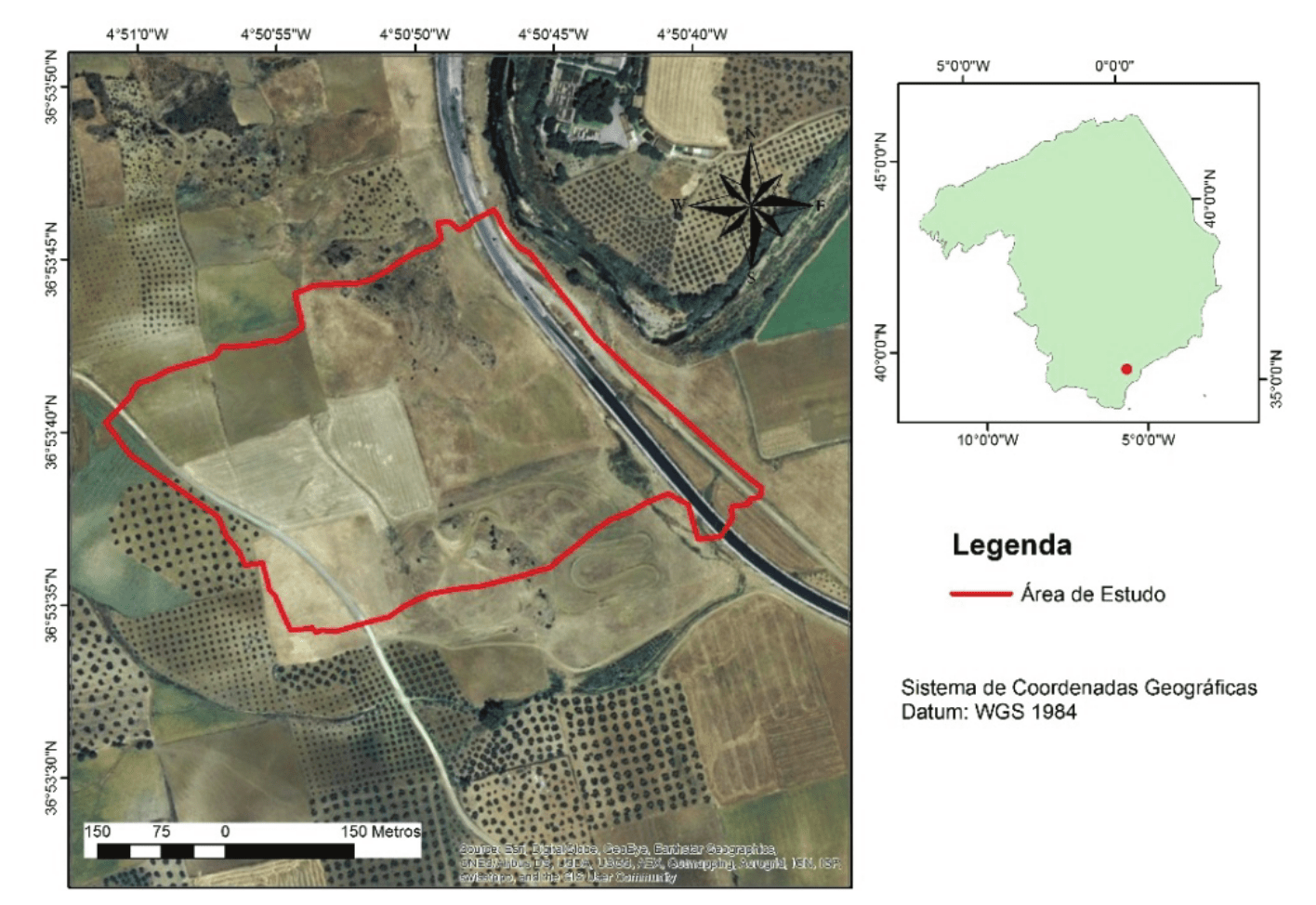
Figure 1.
Study area.

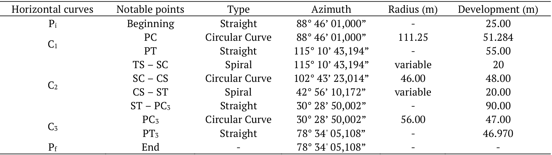
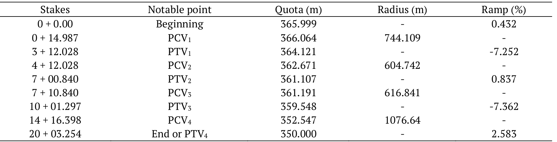
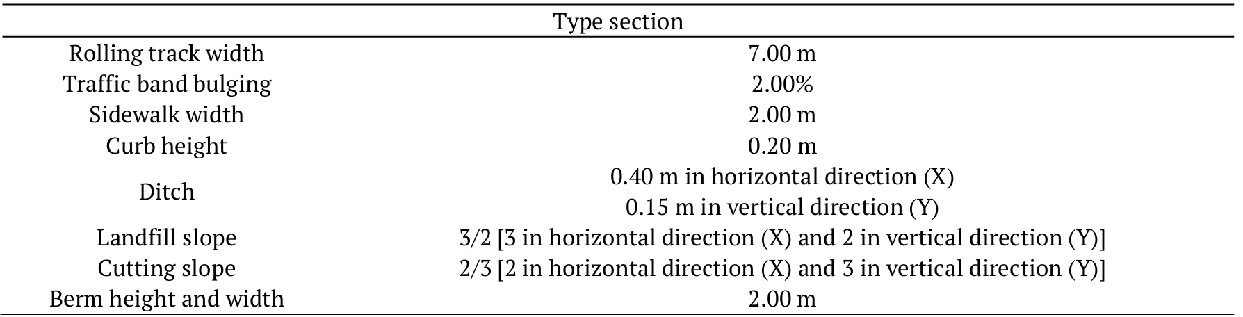
Table 2 and 3 show, respectively, parameters of horizontal and vertical curves.
The type section of the designed road presented the characteristics, illustrated in Figure 2 and detailed in Table 4.
Steps for geometric design
The elaboration of the geometric design of the road proposed and analyzed consisted of the following steps:
• horizontal layout;
• vertical layout;
• superwidth and superelevation; and
• earth movement volume.
Finally, from the results obtained with the analyzed computer programs, they were compared to each other, in function of the standards contained in the technical specifications for road geometric design of the National Department of Transportation Infrastructure, previously represented by the National Department of Roads (Dner, 1999). In view of the above, it was possible to analyze the differences between the softwares in dimensioning the main geometric elements of the proposed road.
Results and discussion
For definition of the geometric elements of the projects developed by the softwares analyzed, it was noticed that the triangulations of the altimetric points of the relief in the study area did not coincide, although the Delaunay triangulation method (TIN) was used for the three computer programs (Figure 3).
The differences may be in the algorithms used to implement this method of triangulation and, consequently, in the interpolation used on this triangulation, since this can insert an uncertainty at the estimated point. Therefore, it is important to know the algorithms implemented in these interpolators that induce to the least error, and consequently, to a better result for calculations of the design elements and a better projection of earth movement volumes of cut and fill (Mazzini & Schettini, 2009; Lopes et al., 2016). According to Botsch, Kobbelt, Pauly, Alliez, and Levy (2010), the algorithms in the different softwares can generate models with badly sampled, redundant vertices or triangles with incoherent shapes, providing contours that do not reproduce the field reality. However, it was observed by Burrough and Mcdonnell (1998), when there is much field information, most interpolation methods produce similar results. In the computer programs analyzed, as a result of the triangulation, coherent contours were generated, except in some places in the horizontal plane, as shown in Figure 4.
In order to construct the horizontal layout of the proposed and analyzed road, the results were similar for the three softwares, that is, the results of stakes, angles and tangents were similar. By analyzing the profiles generated in the three computer programs through an overlap, a small difference (highlighted by an arrow in Figure 5) was observed, possibly caused by differences in triangulations (interpolation method) used in terrain modeling.
The vertical concordances did not present significant differences, with a mean of 0.05 m separation between the results of the analyzed softwares, without variations that could compromise the proposed geometric designs.
In the calculation of superwidth, the computer programs TopoGRAPH and TCP-MDT approached the values recommended by Dner (1999). The AutoCAD Civil 3D software presented values lower than those recommended in 20 cm, considering the recommendations prescribed by Aashto (2011). The designer should be aware of these values, because the analyzed softwares use different references, implying different results for the same parameter examined, as presented in Table 5.
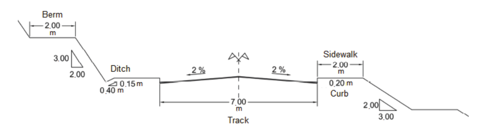
Figure 2.
Components of the cross section of the proposed track.
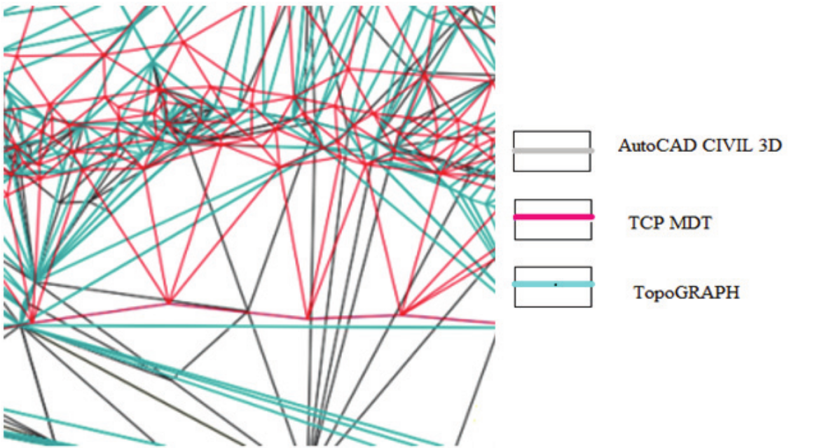
Figure 3.
Overlap of triangulations generated by the analyzed computer programs.
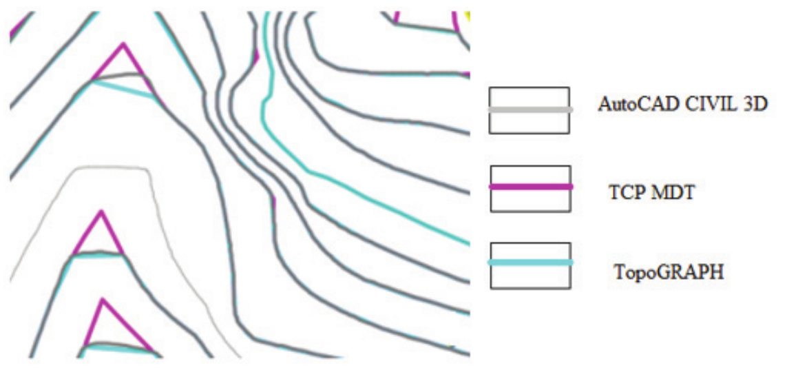
Figure 4.
Overlap of contours resulting from triangulations performed in the analyzed computer programs.
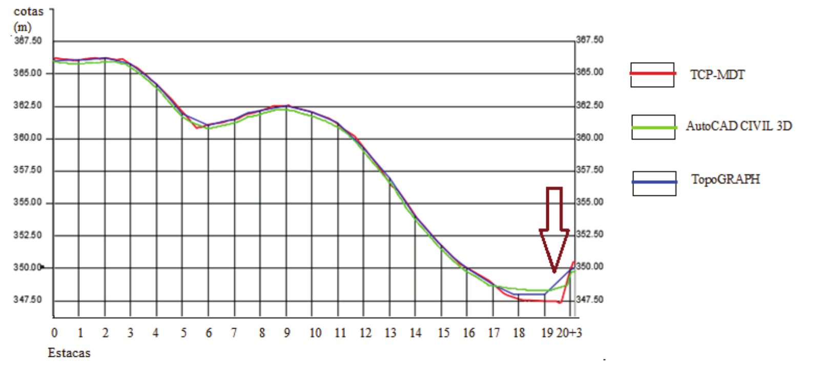
Figure 5.
Visualization of the overlap of the longitudinal profiles generated by the analyzed computer programs.
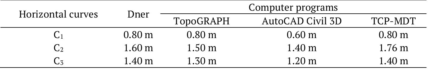
According to Dner (1999), the values of superwidth to be considered in geometric design should be rounded to multiples of 0.20 m and limited to the minimum value of 0.40 m. The current Brazilian technical standards consider that values of superwidth smaller than this limit do not result in relevant practical effects, and may be disregarded. Nevertheless, Aashto (2011) adopts a minimum threshold of 0.60 m, and suggests the exemption of the parameter superwidth for horizontal concordances with radii of curves superior to 250.00 m, in geometric designs with normal width of traffic band of 3.60 m.
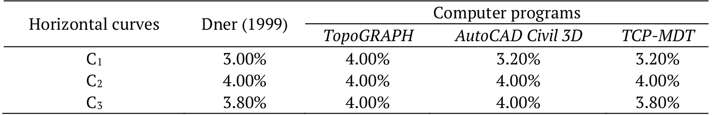
In the calculations to obtain values of superelevation, there was no significant difference for the distribution in plan. In the analyzed softwares, was adopted the Dner (1999) distribution criterion, which was also used by Aashto (2011). This consists of stipulating a value proportional to the transition length of the superelevation, so as to maintain the same superelevation ramp from the beginning with bulging up to where the maximum design superelevation is reached.
However, for the calculation of the maximum design superelevation adopted in the circular sections, the computer program TopoGRAPH did not consider the parabolic distribution recommended by Dner (1999), in the horizontal curve C1. This function considers the minimum radius, the superelevation rate, and the transverse friction coefficients that decrease gradually and simultaneously, up to the radius value of the adopted design (Pontes Filho, 1998; Dner, 1999; Aashto, 2011). This leads to overestimated transverse slopes in the track, compromising the safety and comfort of users in the curve of the designed roadway. For the other two softwares analyzed, the values obtained were close to those recommended by Dner (1999). The difference occurred as a function of the determination of the minimum design radius adopted by each computer program, which depends on the values of the design speed, maximum superelevation and the coefficient of transverse friction (Pontes Filho, 1998; Dner, 1999; Pimenta & Oliveira, 2004;Aashto, 2011). Values of superelevation calculated by the analyzed computer programs, as well as the reference values of Dner (1999) are listed in Table 6.
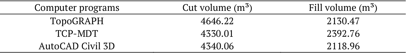
In the analysis of earthmoving projects, according to the volume values of material to be moved in the geometric designs of the route proposed and analyzed, the computer program TopoGRAPH generated a greater cumulative volume of cut. The TCP-MDT software generated a larger cumulative volume of fill. The explanation for this difference is in the terrain modeling. Although the three computer programs analyzed used a TIN model, there is a difference in the triangulation criterion, as shown in Figure 3. This difference may overestimate or underestimate the values of land movement due to altimetric values of the model that are not associated with the actual surface of the terrain (Lopes et al., 2016). Table 7 presents the volumes of cut and fill obtained in the earthmoving projects of the proposed road stretch using the three computer programs analyzed.
The differences in values of cumulative volume of cut and fill presented in Table 7 can be even more significant with the increase in the extension of the paving work of the projected road section. In the values presented in Table 7, the length used for this comparative analysis was approximately 400 m. To minimize this problem, Burrough and Mcdonnell (1998) recommend that, regardless of the computer program used for topographic data processing, the collection of such data should contain as much information as possible about the terrain, reducing differences with respect to the interpolators used by the softwares, making the results more coherent with the field reality
Conclusion
The comparative analysis of the geometric designs developed by TCP-MDT, AutoCAD Civil 3D and TopoGRAPH allowed to conclude that:
• There was no significant difference in the values found for the horizontal and vertical concordances;
• The TopoGRAPH and TCP-MDT were those that approached the values of the superwidth;
• There was no significant difference in the distribution of superwidth between softwares;
• The TopoGRAPH did not consider the distribution of the maximum parabolic superelevation as a function of the radius;
• There were small differences in the cumulative volumes of earth moving, which can become larger with the increase of the longitudinal length of the work.
References
American Association of State Highway and Transportation Officials [Aashto]. (2011). A policy on geometric design of highways and streets. Washington, D.C.: Aashto.
Antas, P. M., Álvaro, V., Gonçalo, E. A., & Lopes, L. A. S. (2010). Estradas - projeto geométrico e de rerraplanagem. Rio de Janeiro, RJ: Editora Interciência Ltda.
Botsch, M., Kobbelt, L., Pauly, M., Alliez, P., & Levy, B. U. (2010). Polygon malha processing. Natick, MA: AK Peters Ldt.
Burrough, P. A., & Mcdonnell, R. A. (1998). Principles of geographical information systems (2 ed.). New York, NY: Oxford University Press.
Departamento Nacional de Estradas de Rodagem [DNER]. (1999). Manual de projeto geométrico de rodovias rurais. Rio de janeiro, RJ: Instituto de Pesquisas Rodoviárias.
Easa, S., & Dabbour, E. (2005). Establishing design guidelines for compound horizontal curves on three dimensional alignments. Canadian Journal of Civil Engineering, 32(4), 615-626. doi: 10.1139/l05-016
Figueira, A. C., Larocca, A. P. C., Quintanilha, J. A., & Kabbach Jr., F. I. (2014). The use of three-dimensional visualization tools to detect deficiencies in geometric roadway designs. Boletim de Ciências Geodésicas, 20(1), 54-69. doi: 10.1590/S1982-21702013000400004
Han, K., Middleton, D., Muzyczka, W. J., Minty, S., & Clayton, A. (2005). Developing virtual reality visualizations to support highway geometric design (3th ed.). Chicago, IL: International Symposium on Highway Geometric Design.
Hassan, Y., Easa, S. M., & Halim, A. O. A. (1998). State-of-the-art of three-dimensional highway geometric design. Canadian Journal of Civil Engineering, 25(3), 500-515. doi: 10.1139/l97-111
Kühn, W., & Hendrick, V. (2010). The new design work – place for the geometric design engineer. In 4th International Symposium on Highway geometric design. Valencia, ES.
Kühn, W., & Jha, M. K. (2006). Using visualization for the design process of rural roads. In 5th International Visualization in Transportation Symposium and Workshop. Denver, CO.
Kühn, W., Volker, H., & Kubik, R. (2011). Workplace simulator for geometric design of rural roads. Transportation Research Board of the National Academies, (2241), 109-117. doi: 10.3141/2241-12
Lopes, E. C., Silva, T. O., Santos, A. P., Ferraz, A. S., Carvalho, C. A. B., & Pitanga, H. N. (2016). Proposta metodológica para modelagem digital de elevação por meio de laser scanning terrestre com ênfase em projetos geométricos de vias. Science & Engineering Journal, 25(1), 137-143. doi: 10.14393/19834071.2016.34274
Mazzini, P. L. F., & Schettini, C. A. F. (2009). Avaliação de metodologias de interpolação espacial aplicadas a dados hidrográficos costeiros quase-sinóticos. Brazilian Journal of Aquatic Science and Technology, 13(1), 53-64. doi: 10.14210/bjast.v13n1.p53-64
Pimenta, C. R. T., & Oliveira, M. P. (2004). Projeto geométrico de rodovias (2a ed.). São Carlos, SP: Rima Editora.
Pontes Filho, G. (1998). estradas de rodagem projeto geométrico. São Carlos, SP: Bidim.
Van Der Horst, A. R. A., & Hogema, J. H. (2011). Driving simulator research on safe highway design and operation. Transportation Research Board of the National Academies, (2248), 87-95. doi: 10.3141/2248-12
Winner, B. H., Ancochea, M., & Graupner, M. (2012). Motion analysis of a wheeled mobile driving simulator for urban traffic situations. In Proceedings of The Driving Simulation Conference Europe (p. 1-8). Arts et Métiers Paris Tech, Paris, FR.
Author notes
emerson.ufv@gmail.br