Informação Tecnológica
Influence of the surface finish on corrosion resistance of stainless steels through machining and remelting on weld bead
Influence of the surface finish on corrosion resistance of stainless steels through machining and remelting on weld bead
Acta Scientiarum. Technology, vol. 41, 2019
Universidade Estadual de Maringá
Recepção: 18 Junho 2017
Aprovação: 10 Abril 2018
Resumo: The TIG Dressing technique has been widely used for repairing cracks in welded structures when subjected to mechanical forces that induce localized fatigue, leading to the collapse during operation. However, this technique has not been used for studies in structures susceptible to corrosion. In addition to changing the microstructure, it is expected that this technique increases the corrosion resistance of the edge of the weld bead which is a vulnerable region to corrosion. Moreover, the machining technique has been widely used to improve the workpieces finishing and/or structures that have been subjected to repair by welding, improving the surface roughness, increasing the corrosion resistance of these structures when subjected to aggressive environments. Thus, this work will study the effects of finishing techniques using machining and welding on the edge of the weld bead joints of 410D ferritic stainless steels, making an evaluation by mass loss in the samples which will be subjected to corrosion by immersion in NaCl containing medium. It is expected that the finishing techniques can relieve tensile stresses increasing the corrosion resistance.
Keywords: ferritic stainless steel, TIG dressing, corrosion
Introduction
According to Roberge (2008), the economic loss caused by corrosion reaches several sectors directly and/or indirectly, increasing maintenance costs and protection processes such as surface coating, generating additional costs for the different productive sectors.
Valdez et al. (2012) argues that the corrosion is a physicochemical interaction, being electrochemical or chemical in nature, between a metal and the medium, resulting in changes in the properties of the metal. Corrosion is generated by direct action of the aggressive agent on the metal. The corrosion reactions in metals can occur in different ways, being the aqueous medium the most frequent occurrence. Corrosion presents in three different stages: anodic process (passage of ions to the solution), displacement of electrons and ions (transfer of electrons from anodic regions to the cathodic by metal circuit and a diffusion of cations and anions in the solution), and the cathodic process (receive electrons by ions or molecules of the solution) (Roberge, 2008).
According to McGuire (2008), stainless steels have a different behavior facing corrosion when compared to carbon steels due to the presence of the passive layer. This layer is composed of hydrated oxides of Cr and Fe, and presents itself in a continuous, non-porous and insoluble form, creating a barrier between the metal and the medium, consequently avoiding wear derived from corrosion. If the protective layer is compromised, for any reason, this layer recovers quickly (repassivation), being often called protective self-sealing layer. It is important to highlight that the repassivation only occurs in oxidizing medium and guaranteed the absence of aggressive agents, such as chlorides. The passivation of stainless steels occurs under specific conditions and depends on several factors: the chemical composition of the steel, its surface conditions and the nature of the medium.
Among the types of corrosion that may occur in a welded joint, the pitting corrosion appears as one of the most damaging in stainless steel when exposed in substantial concentrations of halide ions (Cl-1, Br-1). The pitting may occur due to diverse heterogeneities that occur in metal, for example, chemical composition, texture of the material, internal stresses, among other (Roberge, 2008; Sano, Ambai, Takeuchi, Iijima, & Uchida, 2017).
An important aspect in the choice of the stainless steel for a given application is the corrosion resistance, high mechanical resistance, ductility, weldability, cost, among other factors. Ferritic stainless steels, with relatively low cost, have been an attractive for the development of a new series of these steels, taking into account that the exemption of nickel in the chemical composition and the high chromium content provide high corrosion resistance (Seitovirta, 2013; Mohammed, Reddy, & Rao, 2017).
According to Hu et al. (2011), the main advantage of these steels is the resistance to stress corrosion in chloride containing medium, atmospheric corrosion and oxidation at a low cost. On the other hand, many applications of ferritic stainless steels require the use of welding operations, including the manufacture of household appliances, cookware and laboratory supplies, in high temperature applications, such as exhaust system and the disposal of waste gases from the combustion of petroleum, nuclear industry, among others, where it is necessary to control the parameters and process procedures while minimizing the effects on corrosion resistance, especially in heat-affected zone (HAZ) (Amuda, Akinlabi, & Mridha, 2016).
Studies performed by Revie and Uhlig (2008) showed that in a welded joint, the weld has maximum penetration, the weld bead has contours, shapes, and edges appropriate to minimize the catastrophic effects of the corrosion. Studies have shown that the corrosion process is critical in the region of variance between the weld bead with the base metal due to the concentration level of stresses derived from the welding process (Livieri & Tovo, 2017).
Khatib, Mansouri, Salhi, and Yeznasni (2016) showed that the fillet radius between the welding and the base metal also had considerable influence in generating stresses. Therefore, for these types of joints, a smoother transition between the weld bead and the base metal, forming an angle 180 degrees leads to lower values of stress concentration.
According to Garcia, Martin, Tiedra, Blanco, & Lopez (2008) and Kumar, Balasubramanian, Rajakumar, and Albert (2015), the sensitization of the microstructure and residual stresses can cause the collapse of passive and adherent oxide thin films protecting stainless steels from pitting corrosion. These parameters are related to each other because the existence of tensile stresses generate a rupture of the passive film of sensitized materials (Pujar, Mudali, & Singh, 2011).
The surface finish using machining procedures have been used to minimize the effect of the surface irregularities. However, this procedure only minimizes stress concentration and reduces the surface roughness during the surface finishing. From that instance, it is important to highlight that the machining hardly change the grain size of the heat-affected zone and/or change the micro constituents. On the other hand, welding techniques such as TIG dressing has been used in manufacturing also to improve consistency and the finish of the edge, aiming to reduce the points of stress concentration and, therefore, minimize the occurrence of cracks and increase the resistance to dynamic efforts under fatigue. According to Yan, Chen, and Lin (2016), the benefits achieved by this technique are related to the reduction of the stress concentration in the welding procedure, once the surface discontinuities are removed by the remelting without the use of filler metals.
Zheng, Zhi, and Zhang (2002), using stainless steel (0.03% Cr; 1.0% Si; 2.0% Mn; 0.03% P; 0.02% S; 22% Cr; 5.5% Ni; 3.2% Mo; 0.18% N), evaluated the effect derived by variations in the current and distance between the torches of the dual torch welding using pulsed plasma with TIG remelting on the microstructure and the pitting corrosion. There was more control on microstructure, as result an increase in pitting corrosion resistance.
Based on previously cited experiments, this work aims to show the influence of surface finishing on the adjacent area of the base metal and the weld bead, showing the influence of these techniques on the corrosion resistance of ferritic stainless steel. The mechanical grinding techniques were used on the edge of the MIG welding bead in a restricted device, being compared with unconstrained welds in corrosion resistance, using the method of qualitative assessment by MEV and quantitative mass loss following the G48-76 norm.
Materials and methods
The description of the methodology employed in this work involves the region of the edge of the weld bead as shown in Figure 1.
The chemical compositions of the base metal, provided by ArcelorMittal, and the wire supplied by Weld-inox used during MIG/MAG welding are described in the Table 1. The base metal was used in a plate form, having dimensions of 150 x 200 x 6.35 mm. As for the welding wire, a 1.2 mm diameter wire was used.
For the choice of MIG/MAG welding parameters, with droplet transfer, were performed different welding procedures to find an ideal condition of reinforcement. Found this condition, the welded workpiece have been held in a restricted device as shown in the Figure 2a with the objective of restricting the tensions generated during the welding procedure. The plates had beveled edges with 45° angle and the welds performed towards travel angle 15 degrees. The parameters used to weld stainless steel Ace P410D are in the Table 2 and the Figure 2b shows the weld bead profile in a cross section.
Mechanical grinding by TIG dressing remelt and machining
It was performed TIG welding at the edge of the MIG/MAG weld bead. The welds were done manually using Argon (Ar) as the shielding gas. Preliminarily, it was performed a test of TIG welding on the edge of the weld using plates AISI 1020 carbon steel 25 inches. These were welded using wire ER 70S-6 by varying the current among 6, 10, 15, 20, 30 and 40 amperes. The results obtained showed that the best surface finishing was obtained using current of 10, 20, 30 amperes. Then, the finish was done using the procedure described in Figure 3a. During rectification of the edge of the weld bead, it was used a drill machine at rotation 2800 rpm and a stone gridding to perform the finish as shown in Figure 3b. The samples measure 50 x 25 mm were machined completely by the planer to compare the effect of the convexity of the weld on corrosion.
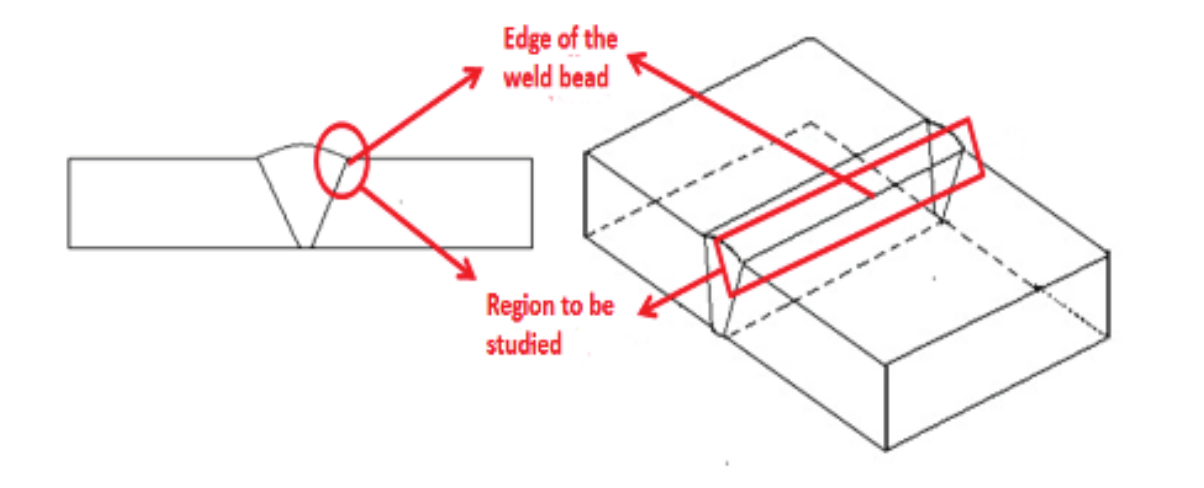
Figure 1.
Edge of the weld bead.
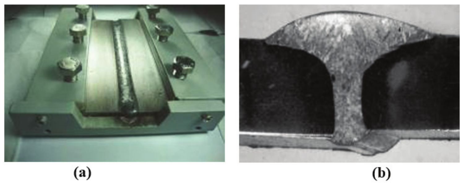
Figure 2.
(a) Welded plates in restricted device; (b) The weld bead profile.


Samples preparation for corrosion test
Corrosion tests were divided into two stages. In the Stage I, the welded plates were sectioned in transversal direction to the weld bead on the dimensions of 25 x 50 mm, following the norm ASTM G48-76 for corrosion test. The samples were machined on the edge of the weld bead with chamfer and without chamfer; with weld bead completely machined and without machining; and only with MIG/MAG welding. For each of the situations, it was cut three samples. Then, they were pierced and weighed considering precision of 0.001 g to calculate the mass loss. The Figure 4 shows how the cutting was performed, and their disposal in the corrosive medium.
In the Stage II, the plates welded using MIG/MAG and TIG, constrained in the welding device. Then, they were immersed in the NaCl solution to check the effect of tensions in the adjacent region x corrosion resistance. The Figure 5 shows the welded plate restricted immersed in NaCl.
Preparation of the medium for the corrosion test
The NaCl solution was prepared according to the norm ASTM G61-86 with pH control for immersion test according to the norm ASTM G51-77. Preliminary tests were performed initially by heating under the following conditions: [1] temperature of 60 ± 2ºC for 20 hours, [2] temperature of 80 ± 2ºC for 10 hours, [3] ambient temperature ± 28ºC for 72 hours. The tests were performed to analyze the ideal condition to study the corrosion process on the edge of the weld bead. From these tests, it was found that the best condition to be used according to the norm G48-76 was the second condition [2].
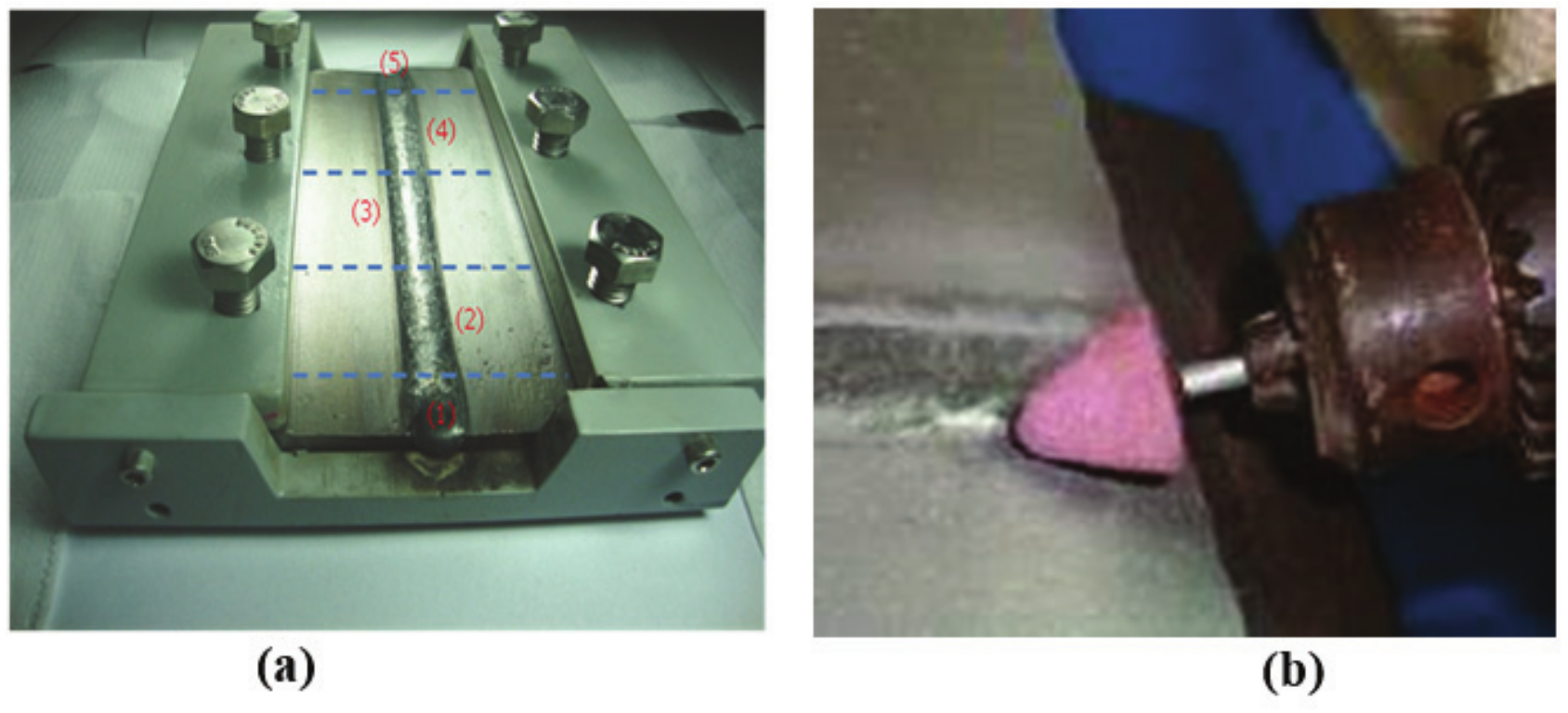
Figure 3.
(a) TIG remelt: (1) and (5) disposed; (2) Remelt with TIG 10 Ampere; (3) Re-melt with TIG 20 Ampere; (4) Remelt with 30 Ampere. (b) Machining.
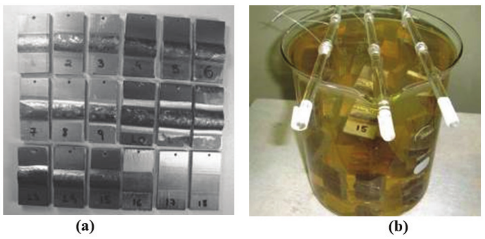
Figure 4.
Samples prepared for corrosion test. (a) cut according to the norm ASTM G48-76; (b) Samples immersed in NaCl containing medium.
Results and discussion
Characterization for optical microscopy of the edge of the weld bead
The edge of the weld bead of the ferritic stainless steel Ace P410 D welded using austenitic wire ER 308 L features the microstructure of Figure 6. The heat-affected zone presents a microstructure with grain growth consisting of martensite with a background of ferrite. The different grain sizes among the regions of welded joint generates various degrees of misalignment among adjacent grains so that the magnitude of the energy of adjacent grains depend of the disorientation degree, being greatest for outlines of large angles (Callister, 2013). In this way, the interfacial energy total is lesser in materials with large grains than in materials with finer grains, which is more susceptible to corrosion. On the other hand, these steels for having body-centred cubic structure, suffering high loss of toughness with the high growth of grain. According to Amuda et al. (2016), the most common form to control this growth is through the addition of stabilizers (Ti, Nb) and to keep tracking the welding power, so that the smaller the energy, the lesser is the grain growth.
Characterization for MeV of the edge of the weld bead Step I
The edge of the weld bead is the region more susceptible to corrosion by a number of factors, among them: no correlation between the weld bead x plate, residual stresses derived from the welding process, difference in grain size and the presence of micro constituents and microphase which are the main causes of pitting corrosion processes in this region (Brinksmeier, Preuss, Riemer, & Rentsch, 2017). When exposed to chloride ions containing medium, the ferritic stainless steels develop specific type of corrosion depending on the conditions of the environment and the region being considered. In order to show the different superficial changes of the edge of the weld bead, the samples were subjected to the corrosion test using sodium chloride (NaCl) heated to the temperature 80 ± 2ºC for 10 hours in the welding conditions below.
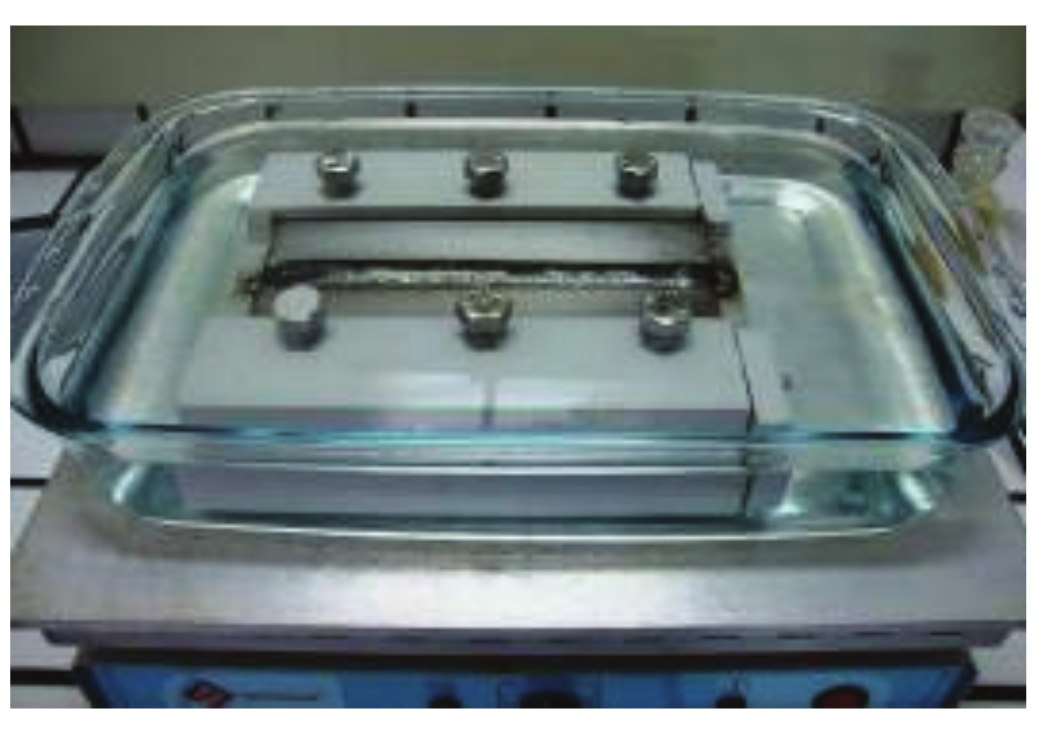
Figure 5.
Plate welded by MIG/MAG process, immersed in NaCl.
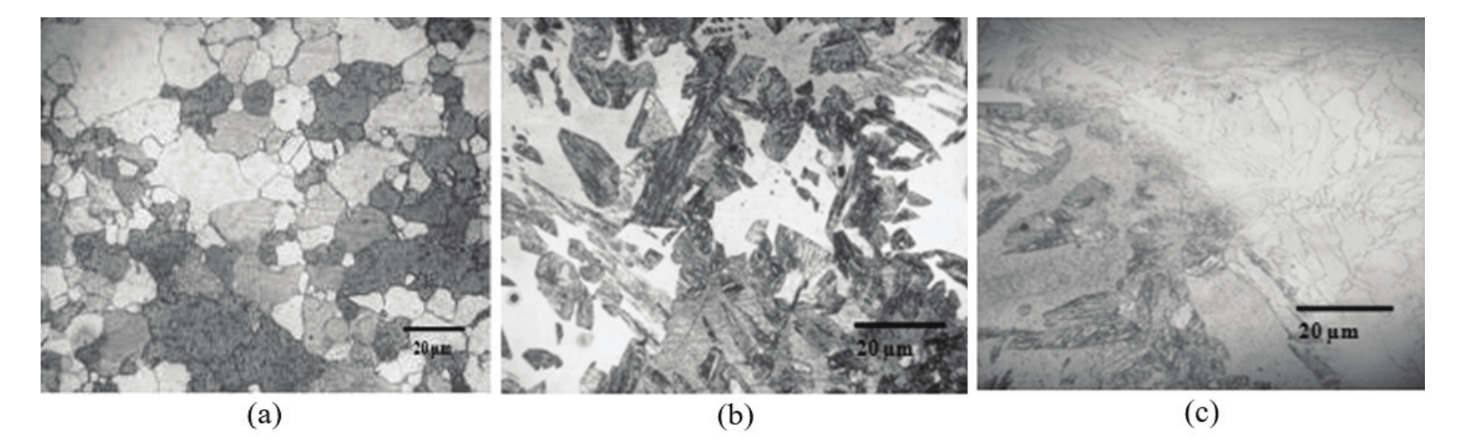
Figure 6.
Microstructure of the welded joint. (a) Base Metal; (b) Heat-affected zone (HAZ); (c) Interface HAZ/MZ (molten zone). Attack: Aqua Regia.
MIG/MAG chamfer 45º degree and MIG/MAG bottom site of the plates with and without edge rectification
Figure 7 shows the result of the scanning electron microscopy of samples after immersion in sodium chloride containing medium for 10 hours. It is observed that the welded samples with MIG welding presented an opening at the adjacent interface of the weld bead x plate as a result of the corrosive agent. In the MIG joint over the plate, it was observed cracks along the weld bead which can be associated to the low fillet angle of the weld bead x plate, generating a greater concentration of tensions. The excessive convexity observed both at the top as the bottom of the weld doesn't appear to be a discontinuity, however there is an increased concentration of stresses in the welded joint and may lead to crack formation (Livieri & Tovo, 2017). Khatib et al. (2016) showed that the fillet radius between the weld bead and the base metal also has a considerable influence as to generate stress, the latter tending to decrease with the increase of the former variable.
Figure 8a and d shows the different forms of the surface finishing on the edge of the weld bead using grinding tungsten stone and widia stone. It is observed that the surface roughness was determined by the form of the surface finish. This turned to be an important factor in the corrosion resistance of the samples subjected to the rectification process. By the morphology of the pitting shown in Figure 8b and d, it is observed smoother finish using rectification with widia tip, leading to formation of shallower pitting when compared with the finish obtained from the tungsten tip. The chemical elements that constitute the pitting of the Figure 8b shows the presence of Silicon in greater quantity, being a stabilizer element of the Ferrite, as a result, increasing corrosion resistance. On other hand, the presence of chlorine contributes to accelerate the corrosion process. Studies conducted by Gravalos, Martins, Diniz, and Mei (2010), found that the pitting corrosion resistance has been correlated with the morphological conditions of surface, where the smooth surface finish helps to decrease the potential for pitting initiation. Brinksmeier et al. (2017) also noted that parameters of machining process used correctly in finishing of welded joints have increased pitting corrosion resistance in medium containing chloride ions.
Another point to be considered is that this technique creates a smooth transition between base metal and weld metal, increasing the correlation of the welded joint, minimizing the concentration of stresses that cause cracks, contributing to an increase in the corrosion resistance of that region.
MIG/MAG with 45 degree chamfer remelted edge by TIG process
Figure 9a and b show the surface of heat-affected zone remelted by TIG welding and subjected to the corrosion test in NaCl containing medium heated to 80 ± 2ºC for 10 hours. It is possible to observe the formation of pitting in all extension of the HAZ, however, this technique has generated a smooth transition weld bead x plate, decreasing the tensions generated in this region. According to Yan et al. (2016), the benefits achieved by this technique are related to the reduction of the concentration of the welding voltage, once by the remelt, without the use of filler metals, the surface discontinuities are removed, which can lead to the increase of the corrosion resistance. In addition to removing surface discontinuities, this technique controls the microstructure which can lead to greater resistance to corrosion (Olson, Lieberman, & Saxena, 2013). However, the microstructure and the mechanical properties of the recast layer vary depending on the kinetics of solidification. The welding energy imposed on TIG and the time length of interaction during remelt are the main factors influential in the microstructure. The maximum surface temperature may not reach a range of intense vaporization. If it is required a minimum thickness of the recast layer, the time length of interaction cannot be reduced significantly.
Characterization for MeV of the edge of the weld bead of the Step II
In the step II the evaluation of corrosion wear on the edge of the cord was made in restricted boards soldered with MIG/MAG welding, being compared with remelted welds by TIG welding after soaking in a NaCl containing medium by 10 hours heated up to ± 80°C. Figure 10a and c show the result of MIG/MAG and MIG/MAG remelted by TIG after the corrosion test. It is observed that the formation of cracks in the HAZ in both cases after the corrosion test and that these cracks occurred to a lesser extent on the plate remelted by TIG welding. According to Siqueira Filho et al. (2013), the residual voltages of traction when restricted, can develop fracture, stress corrosion, and reducing the fatigue resistance. On the other hand, the result of EDS, Figure 10b shows that the corrosive product from MIG welding restricted a large amount of manganese appeared which may have contributed to increase the embrittlement of the HAZ leading to the formation and propagation of cracks. According to Garcia et al. (2008) and Pujar et al. (2011), the residual stresses can cause the collapse of the thin films of magnetic oxide and passive that protect the stainless steel from corrosion, and may lead to fracture of the material when exposed in chloride ions containing mediums.
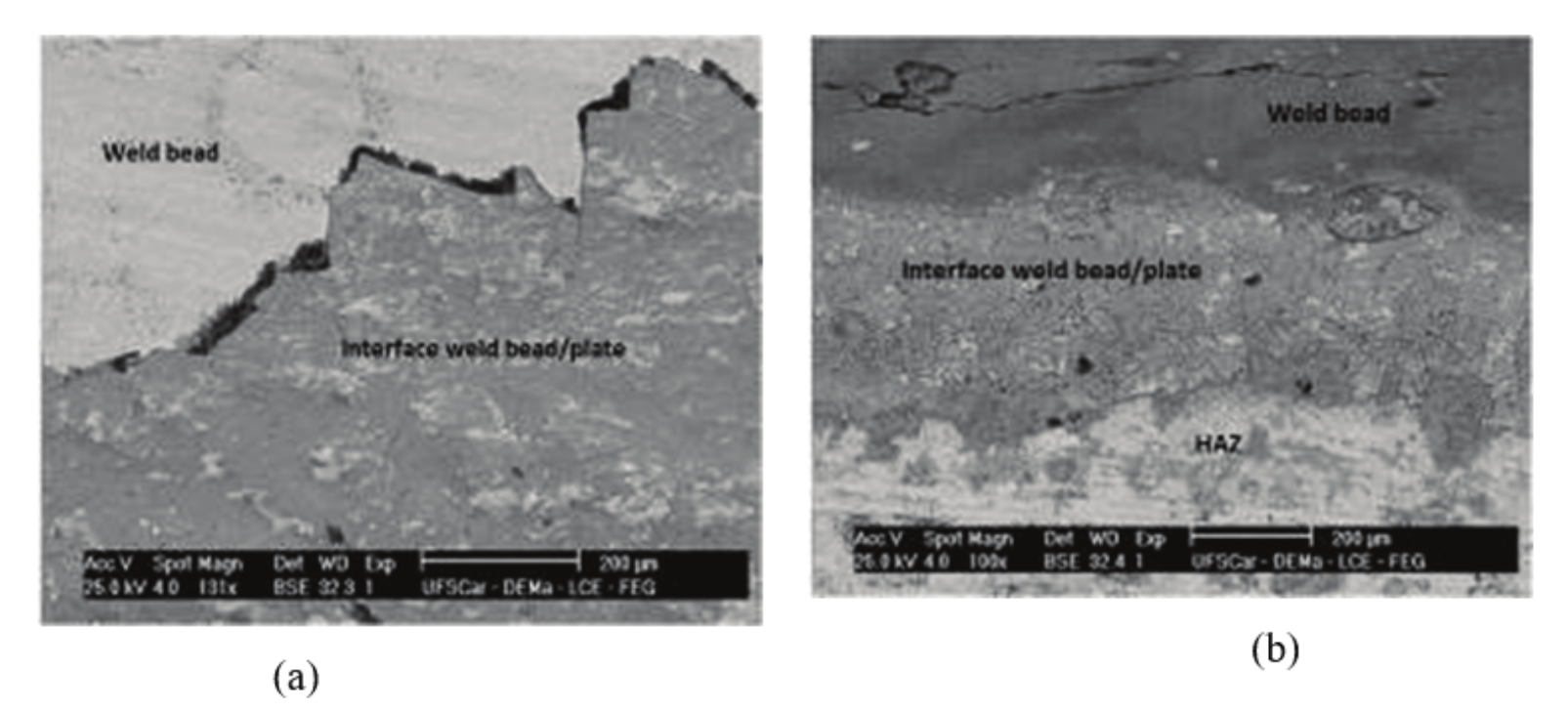
Figure 7.
Samples subjected to the corrosion test in NaCl heated to 80 ± 2ºC for 10 hours. (a) MIG/MAG Welding at 45° bevel; (b) MIG/MAG Welding the under the plate.
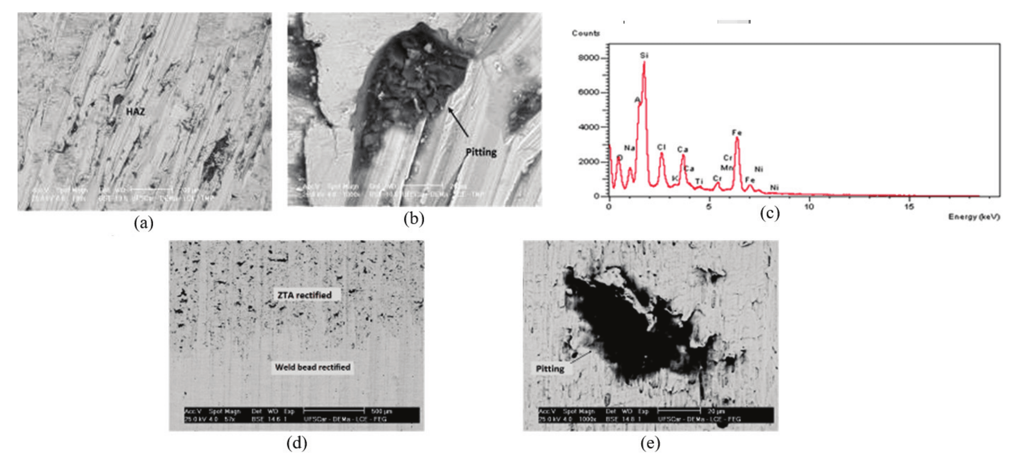
Figure 8.
Samples subjected to the corrosion test in NaCl containing medium heated to 80 ± 2ºC for 10 hours. (a) rectified using tungsten tip; (b) Heat-affected zone morphology of the pitting after rectification and subjected to the corrosion test NaCl containing medium; (c) the pitting EDS of (b); (d) Sample fully rectified with the planer; (e) morphology of the pitting on (d).
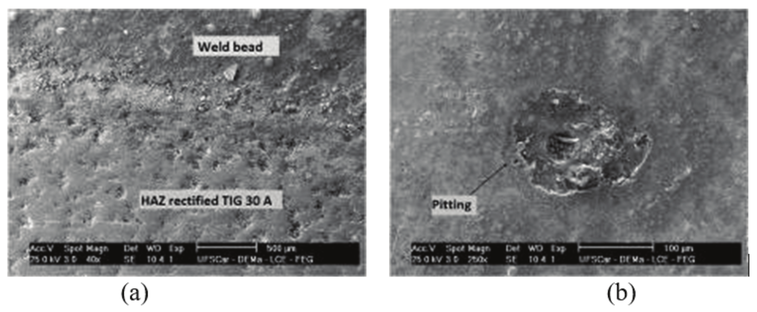
Figure 9.
Samples subjected to the corrosion test in NaCl heated to 80 ± 2ºC for 10 hours. (a) HAZ remelted by TIG welding, current 30 ampere; (b) Morphology of the pitting after remelt and subjected to the corrosion test in NaCl containing medium.
Mass loss of the samples of the Step I
The samples of the step 1 were subjected to mass loss as shown in Figure 11 after corrosion test in NaCl containing medium heated to 80 ± 2ºC for 10 hours. It is observed that the smallest mass loss happened with fully machined samples and the highest mass loss occurred in the remelted samples welded using TIG 20 ampere. Stresses resulting from adjacent region connecting the weld metal and the plate were eliminated by the machining of the weld bead. This may have contributed to a greater resistance to corrosion. The influence of the current applied to remelt the border proved to be an important variable to soften the adjacent region of the welded joint and it is necessary to adjust this parameter to control the grain size and the formation of constituents that may contribute to increase the corrosion resistance in the region under study.
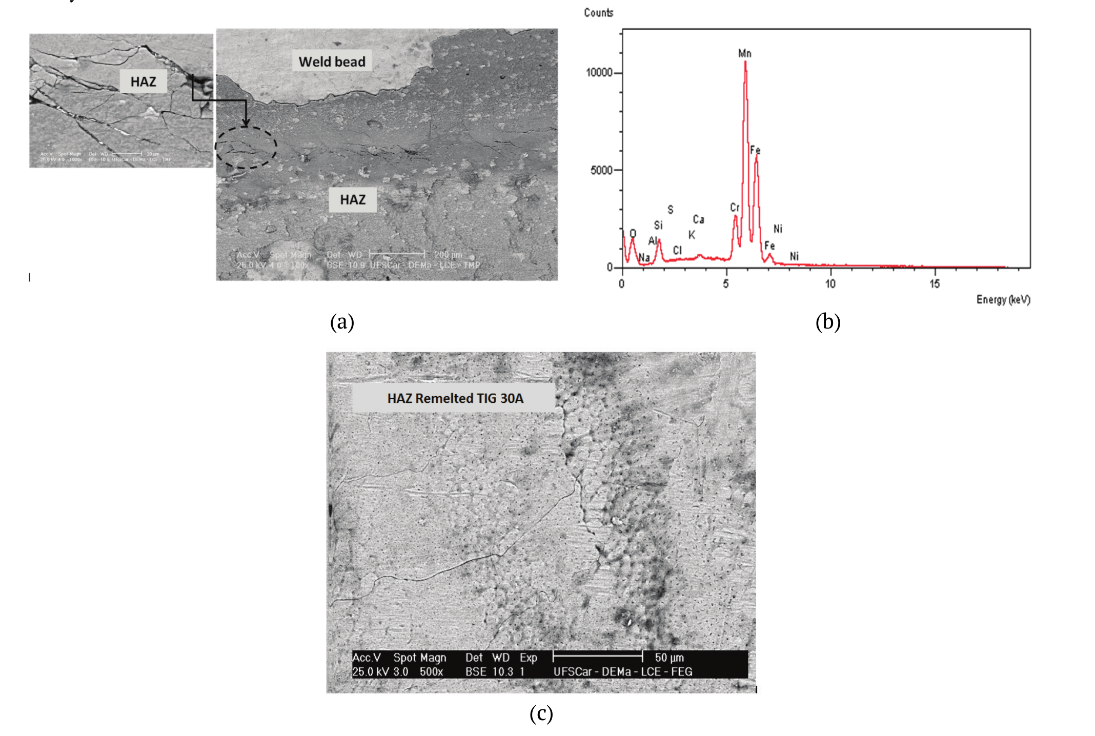
Figure 10.
Constrained plates subjected to the corrosion test in NaCl containing medium, heated to 80 ± 2ºC for 10 hours. (a) Interface HAZ/MZ (molten zone); (b) EDS in (a); (c) HAZ remelted by TIG welding 30 ampere.
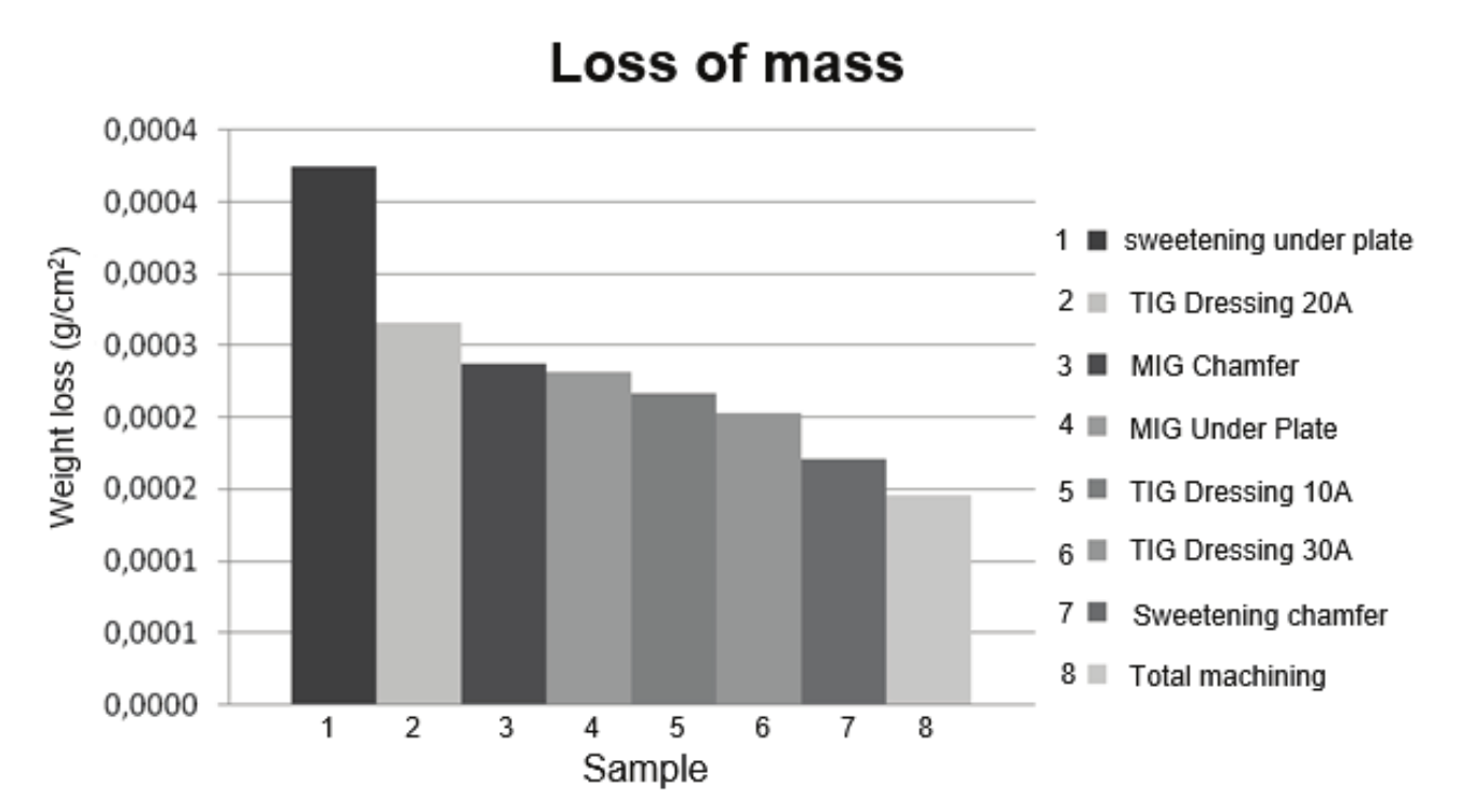
Figure 11.
Samples subjected to mass loss in NaCl containing medium heated up to 80 ± 2ºC for 10 hours.
Conclusion
Mechanical grinding techniques used to improve the consistency between the weld bead and the plate had distinct surface finishing, which influenced the final result of the corrosion resistance.
Corrosion resistance on the edge of the weld bead was, also, influenced by the way in which the samples were subjected to the corrosion test, constrained or unconstrained. The constrained condition presented different corrosion shapes from the unconstrained using the same conditions of the sodium chloride containing medium (NaCl).
The finishing of the adjacent region between weald bead and base metal by machining, turned out to be dependent on the type of tool used in the procedure, which will influence the roughness and corrosion resistance.
It was evident that the corrosion resistance of the edge of the weld bead using remelt with TIG welding presented variations in response to the welding current. This turned to be an important variable to control the stress, grain size and micro constituents.
The mass loss of samples subjected to immersion in sodium chloride containing medium was lower for those that were fully machined and higher for samples sweetened under plate.
Acknowledgements
The authors are grateful to the Research Support Foundation of the State of Maranhão (Fapema), the Coordination for Improvement of High Education and Personnel (Capes), Federal University of São Carlos (UFSCar), the Federal University of Uberlândia (UFU) and the Federal Institute of Education, Science and Technology of the State of Maranhão (IFMA).
References
Amuda, M. O. H., Akinlabi, E. T., & Mridha, S. (2016). Ferritic stainless steels: metallurgy, application and weldability. Reference Module in Materials Science and Materials Engineering, 3(4), 41-66. doi: 10.4028/www.scientific.net/KEM.69-70.167
Brinksmeier, E., Preuss, W., Riemer, O., & Rentsch, R. (2017). Cutting forces, tool wear and surface finish in high speed diamond machining. Precision Engineering, 49, 293-304. doi: 10.1016/j.precisioneng.2017.02.018
Callister, W. D. Jr. (2013). Materials science and engineering: an introdution (9th ed.). Danvers, MA: John Wiley & Sons.
Garcia, C., Martin, F., Tiedra, P., Blanco, T. Y., & Lopez, M. (2008). Pitting corrosion of welded joints of austenitic stainless steels studied by using an Electrochemical Minicell. Corrosion Science, 50(4), 1184-1194. doi: 10.1016/j.corsci.2007.11.028
Gravalos, M. T., Martins, M., Diniz, A. E., & Mei, P. R. (2010). Influence of roughness on the pitting corrosion resistance of turned superaustenitic stainless steel. Revista Escola de Minas, 63(1), 77-82. doi: 10.1590/S0370-44672010000100013
Hu, C., Xia, S., Li, H., Liu, T., Zhou, B., Chen, W., & Wang, N. (2011). Improving the intergranular corrosion resistance of 304 stainless steel by grain boundary network control. Corrosion Science, 53(5), 1880-1886. doi: 10.1016/j.corsci.2011.02.005
Khatib, H., Mansouri, K., Salhi, B., & Yeznasni, A. (2016). Fatigue strength analysis of welded joints using an experimental approach based on static characterization tests. Contemporary Engineering Sciences, 9(11), 513-530. doi: 10.12988/ces.2016.6320
Kumar, M. V., Balasubramanian, V., Rajakumar, S., & Albert, S. K. (2015). Stress corrosion cracking behaviour of gas tungsten arc welded super austenitic stainless steel joints. Defence Technology, 11(3), 282-291. doi: 10.1016/j.dt.2015.05.009
Livieri, P., & Tovo, R. (2017). Analysis of the thickness effect in thin steel welded structures under uniaxial fatigue loading. International Journal of Fatigue, 101(2), 363-370. doi: 10.1016/j.ijfatigue.2017.02.011
McGuire, M. F. (2008). Stainless steels for design engineers. Ohio, US: ASM International.
Mohammed, R., Reddy, G. M., & Rao, K. S. (2017). Welding of nickel free high nitrogen stainless steel: Microstructure and mechanical properties. Defence Technology, 13(2), 59-71. doi: 10.1016/j.dt.2016.06.003
Olson, G. B., Lieberman, D. S., & Saxena, A. (2013). Proceedings of the International Conference on Martensitic Transformations (ICOMAT). Santa Fe, NM: The Minerals, Metals and Materials Society.
Pujar, M. G., Mudali, U. K., & Singh, S. S. (2011). Electrochemical noise studies of the effect of nitrogen on pitting corrosion resistance of high nitrogen austenitic stainless Steels. Corrosion Science, 53(12), 4178-4186. doi: 10.1016/j.corsci.2011.08.027
Revie, R. W., & Uhlig, H. H. (2008). Corrosion and corrosion control. An introdution to corrrosion science and engineering (4th ed.). Danvers, MA: John Wiley and Sons, Inc.
Roberge, P. R. (2008). Corrosion engineering: principles and practice. New York, US: The Mc Graw-Hill Companies.
Sano, Y., Ambai, H., Takeuchi, M., Iijima, S., & Uchida, N. (2017). Effect of chloride ion on corrosion behavior of SUS316L-grade stainless steel in nitric acid solutions containing seawater components under γ–ray irradiation. Journal of Nuclear Materials, 108, 163-184. doi: 10.1016/j.jnucmat.2017.06.017
Seitovirta. M. (2013). Handbook of stainless steel. Avesta, SW: Outokumpu Stainless AB.
Siqueira Filho, A. V., Yadavaa, Y. P., Cardoso, F. I. B., Guimarães, P. B., Maciel, T. M., & Ferreira, R. A. S. (2013). Development of methodology for measurements of residual stresses in welded joint based on displacement of points in a coordinated table. Materials Research, 16(2), 322-326. doi: 10.1590/S1516-14392013005000001
Valdez, B., Schorr, M., Zlatev, R., Carrillo, M., Stoytcheva, M., Alvarez, L., Rosas, N. (2012). Corrosion control in industry, environmental and industrial corrosion - practical and theoretical aspects. Rijeka, CR: InTechOpen.
Zheng, L. W., Zhi, X. W., & Yu, Z. (2012). Study on Welding Parameters Optimization of Duplex Stainless Steel 2205 Based on Orthogonal. Advanced Materials Research, 472-475, 1305-1308. doi: 10.4028/www.scientific.net/AMR.472-475.1305.
Yan, F., Chen, W., & Lin, Z. (2016). Prediction of fatigue life of welded details in cable-stayed orthotropic steel deck bridges. Engineering Structures, 127, 344-358. doi: 10.1016/j.engstruct.2016.08.055
Autor notes
jrobert@cct.uema.br