Informação Tecnológica
Received: 01 August 2017
Accepted: 25 October 2018
DOI: https://doi.org/10.4025/actascitechnol.v41i1.39046
Abstract: The present paper seeks to enhance the potential damage detention and location of the discrete wavelet transform (DWT) in a thin laminated composite damaged by a signal derived from vibration modes. The DWT-1D is used to spatially identify (x-y plane) the damage location. The matrix damage level occurs during the impulsive load application over the analyzed structure. The finite element used is a Serendipity-type element with a rectangular shape, eight nodes and five mechanical degrees-of-freedom per node, and is formulated by First-order shear Deformation Theory (FSDT). The dynamic equation of motion including internal damage is solved by the Newmark implicit integration method, considering small deformations. The results have demonstrated that discrete mother wavelets applied in dynamic modal signal processing are capable of detecting a small damage magnitude in the matrix level. The wavelet coefficients reached great amplitudes in the damaged area.
Keywords: wavelet analysis, cracked composite plates, FSDT, Finite Element Method.
Introduction
The analysis of the component materials within a structure during its life cycle is known as SHM (Structural Health Monitoring). The main SHM goal is to detect and describe possible changes in the structural system under normal operational conditions and using non-destructive methods, contributing to minimize repairing and maintenance costs, to provide a better level of safety to the users, and to avoid possible catastrophic failures (Stark, 2005). Within the category of SHM methods, there exist: acoustic emission, radiography, Lamb waves, natural frequencies, electro mechanic impedance, among others (Giurgiutiu & Santoni-Bottai, 2011). According to Katunin and Holewik (2013) and Rhif, Abbes, Farah, Martínez, and Sang (2019), another largely applied SHM method is the Wavelet Transform (WT), due to its efficiency at identifying insignificant singularities of signals and waves.
According to Stark (2005) and Limongelli and Çelebi (2019), WT studies have first initiated during the middle 80s, when signs originated from seismic activities and earthquakes have brought the necessity of studying such waves using a more precise method than the one developed by the Fourier Transform. One of the greatest advantages of this method over the others is that any data acquisition system and a portable microcomputer may be used to either real-time or non-real-time monitoring of a given structure.
Two different WT approaches, the Continuous Wavelet Transform (CWT) and the Discrete Wavelet Transform (DWT), are the most widespread methods within the scientific literature when it comes to detecting damage in general structures. The work done by Wang and Deng (1999) is considered the pioneer study dealing with damage diagnosis in two-dimensional structures (2D) using CWT. They have adopted the mother wavelet Haar to detect the damage on metallic beams and plates, analytically modeled, inserted through a crack formation. Chang and Chen (2004) have applied a 1D CWT to the fundamental vibration mode of a metallic plate, separately in spatial directions x and y. The same author has utilized a Garbor wavelet in the dynamic signal processing (vibration mode) obtained from the plate’s finite element model, and has achieved satisfactory results on the damage detection. However, the author has identified that the wavelet coefficients are influenced by the plate’s boundary (edge) effect, which makes his proposed methodology unfeasible for damage identification next to the plate. Other studies suggest using DWT (2D) for damage detection in two-dimensional structures, such as the one developed by Loutridis, Douka, Hadjileontiadis, and Trochidis (2005), who has used it in the decomposition of metallic plates vibration modes to determine the damage depth, location and length, inserted as a crack on the structure. Yang, Yang, and Tseng (2011) have applied a Packet DWT (2D) into aluminum plates reinforced with stiffeners for the numerical and experimental damage detection. The Packet wavelet allows the signal’s separate decomposition in the horizontal, vertical and diagonal directio-ns, identifying singularities (damages) along. Within the current state of the art of damage identification in composite structures using WT, there are few works. Yan and Yam (2002) have achieved solid results for damage detections in composite plates with piezoelectric materials. The acquired voltage in the piezoelectric sensors are processed by the WT to detect the damage once determined in the composite matrix. Nevertheless, the authors have not performed a model of damage development over time, that is to say, the proposed model’s parameters are constant.
The DWT demands less computational time consumption compared to the CWT when it comes to signal processing, and is then preferable for online damage monitoring on structures. Furthermore, the CWT requires a scale-parameter definition for the correct damage location.
One of the goals the present paper aims to achieve is the numerical implementation of a Finite Element Method - FEM - formulation considering a time and scalar variable (called D) for modelling damaged laminated composite structures, and also to evaluate a reliable methodology for detecting and locating the degree of damage severity in laminated composite plates. The aforesaid methodology is based upon a DWT applied to dynamic signals (vibration modes) of damaged laminated composite structures. The structure selected for the numerical analyses in this paper is a laminated composite plate. The damage state of such structure is obtained after the application of an impulsive load (time-varying) and, once this is entirely applied, the mass and stiffness matrices of the structure in damage state are generated. These matrices are further employed in determining the vibration modes of the laminated composite plate in damage state. The vibration modes are in turn utilized as the signal to be transformed by the DWT with the purpose of identifying the area of the composite plate that has been damaged by the impulsive load. Especial attention is given to the temporal damage mechanism herein implemented since there have been few studies assessing this subject in the current scientific literature review. This mechanism particularly occurs in the laminate matrix and consists of an impulsive load applied to the laminated composite plate, being formulated using the Thermodynamics of Irreversible Processes.
This paper contributes to the SHM of laminated composite plates in that it proposes an innovative use of a progressive damage mechanism, i.e. time-varying, associated to a non-destructive SHM technique based upon the analysis of vibration modes of the structure transformed via DWT. Very few works have tackled the issue of associating these two subjects, that is to say, a time-varying damage mechanism (to the level of the laminate matrix) and a SHM technique using DWT, for the detection and location of matrix damages in laminated composite materials.
Material and methods
This work makes use of a 1D DWT directly applied to the vibration modes of a given damaged laminated composite structure for the spatial obtainment of the wavelets coefficients (WC), consecutively adopted for damage detection and location through their singularities peaks. The eigenvectors, represented by the vibration modes of the structure, are straightly decomposed by the considered 1D DWT, and are then applied to the spatial depiction of the wavelets coefficients.
FEM-FSDT formulation
Finite Element Method (FEM) provides the development and use of a model accurately close to the real mechanical behavior of damaged composite materials, and in a more efficient manner than the majority of models once used in SHM-WT works. Besides, FEM demonstrates higher modeling flexibility of composite structures under disparate boundary constraints, load applications, weather and usage conditions.
The adopted theories that numerically model composite structures using FEM are subdivided into the following families: Equivalent Single Layer Theory (ESLT) and Layerwise. This paper makes use of the First-order Shear Deformation Theory (FSDT), from the ESLT family, since it is extensively used for modeling thin laminated composite structures herein presented. Few recent works adopting the FSDT theory in the modelling of structures made of composite materials include, for instance, the studies of Zhang, Shi, Zha, and Wang (2018), Zhai, Li, and Liang (2018) and Kahya and Turan (2018).
The FSDT numerical verification and implementation used in this paper are presented by Faria and Lima (2014). However, this last work did not consider the damage mechanism incorporation in the FSDT formulation.
The formulation of FSDT theory using FEM (FEM-FSDT) and incorporating the matrix damage mechanism (Damage FSDT-FEM) in the laminate presented in this paper is summarized in the following sections.
The mechanical behavior of a composite structure is mathematically approximated using FSDT theory by a first-order field displacement, expressed in Equation 1:
 (1)
(1)where:
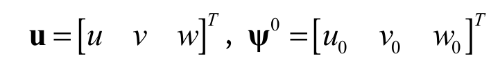 , and
, and 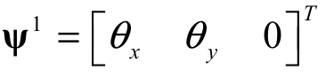 ; uo,
vo
and wo are the displacements
along the coordinate directions (x, y, z)
of a material point in the reference plane (x,
y, 0) from the laminated composite structure; and are respectively normal
segments rotations in relation to the reference surface around the elementary axis
x and y.
; uo,
vo
and wo are the displacements
along the coordinate directions (x, y, z)
of a material point in the reference plane (x,
y, 0) from the laminated composite structure; and are respectively normal
segments rotations in relation to the reference surface around the elementary axis
x and y.
The present work implements a finite element known as ‘Serendipity’ (Bathe, 2014). It is a planar and rectangular finite element on which every edge presents three nodes, totaling 8 nodes. The mechanical variables indicated in Equation 1 are further converted to its finite element formulation using appropriate shape functions (Ni, i = 1:8, provided by Zienkiewicz, Taylor, & Zhu, 2013) of the adopted finite element.
The formulation of elementary matrixes is possible by using ‘Hamilton’s Vibrational Principle’ (Bathe, 2014). This principle allows the total incorporation of energetic contributions presented on a given structure, and two equations are obtained to express mass and stiffness matrixes in an elementary level and written based on local coordinates, according Equation 2 and 3:
 (2)
(2)
 (3)
(3)where:
Me is the elementary mass matrix, and Ke is the elementary stiffness matrix (dependent on the ‘scalar damage variable D’). nk is the total number of layers k along the laminate thickness, pk the density of a material from a particular layer k, and C the matrix of constants of elasticity dependent on the scalar damage variable D.
The changing process of the local coordinate elementary (x-y)
to the system (, ) one is accomplished by
using the ‘Jacobian of the transformation’, expressed as 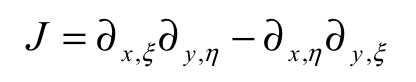 ( Zienkiewicz et al., 2013).
The eight shape functions of the ‘Serendipity’ finite element, provided by Zienkiewicz et al. (2013), are also included in the function matrix N.
Damage FEM-FSDT formulation
The appearance of micro-cracks over the laminate matrix is considered the first damage mechanism to induce variations on the mechanical properties of laminated composite structures ( Talreja & Singh, 2012), consequently affecting their dynamic properties (natural frequencies, modal damping, modal shapes, among others).
In the particular case of an orthotropic material, which presents nine independent coefficients of elasticity, the matrix of constants of elasticity C(D) in a damaged state and developed in the material reference system can be expressed in Equation 4 ( Boubakar, Trivaudey, Perreux, & Vang, 2002):
 (4)
(4)where:
C1 is the matrix of elastic constants in a damaged state, which is the inverse of the sum between S, the flexibility matrix in a non-damaged circumstance, and H(D), the damage matrix containing the ‘density functions of microcracks’ previously expressed in terms of the scalar damage variable D. The coefficients from the flexibility matrix S are notified by Zienkiewicz et al. (2013).
Damage stimulates a loss of mechanical stiffness, mathematically represented by the modification on the matrix of elasticity constants of the composite material C1(D), as indicated in Equation 4. The damage law is further associated to the calculation of one sole internal damage scalar variable (D), valid for materials with an expressed transversal isotropy. In a non-damaged state D = 0, while in a damaged state 0 < D < 1, and for an absolute failure condition on a given composite structure D = 1.
The development law of the damage mechanism, also known as load function, is expressed under the Boubakar et al. (2002) and is expressed in terms of ‘Thermodynamics of Irreversible Processes’. In that equation, the damage matrix H(D)is dependent upon the scalar variable D, which is ‘in turn associated to each micro-crack opening mode and is expressed according to the following Equation 5 (Boubakar et al., 2002):
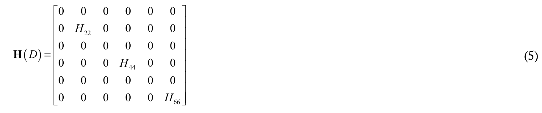 (5)
(5)where:
H22 = S22 (D/(1 – D)),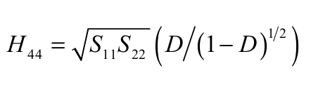 and H66 = S22 (D/(1 – D)1/2).
Dynamic equation of motion of a damaged system
Considering the connectedness between the nodes and implementing the standard procedure for assembling the global matrixes, the mathematical model of the global equation for displacements of a damaged system can be expressed as follows, excluding the laminate inherited damping since it deals with dynamic loading (Bathe, 2014), according Equation 6:
 (6)
(6)where:
M is a global mass matrix from the composite structure, K (D(t)) is the ‘global stiffness matrix’ considering the recommended non-linear damage mechanism ( Boubakar et al., 2002), f (t) is a ‘vector of external loads’.
The elastic behavior of the matrix K (D(t)) (Equation 6) is modified by matrix C1(D(t)) (Equation 4) due to the formation and evolution of micro cracks and cavities (whose damage evolution law will be further exposed) during the loading f (t) application.
Within dynamic analysis
under free vibrations modes, Equation 6 is manipulated assuming the global vector
of external loads f (t) as being
zero and adopting a periodic solution expressed in the form of 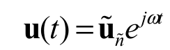 , the real part of which simply represents the harmonic response
as
, the real part of which simply represents the harmonic response
as 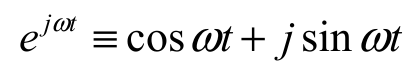 (Zienkiewicz et al., 2013). Thus, Equation 6 can be
now changed to the following in Equation 7:
(Zienkiewicz et al., 2013). Thus, Equation 6 can be
now changed to the following in Equation 7:
 (7)
(7)where:
The vectors  and
and the scalars are respectively called normal modes of the system (or ‘eigenvectors’ or ‘vibration modes’) and ‘eigenvalues of the system’, N represents the total number of degrees of freedom of the system whose size of the matrices M and K are N x N and tf is the ending time of the external load f(t) application to the composite structure.
For non-zero solutions, the determinant of the above coefficient matrix (Equation 7) must be zero ( Zienkiewicz et al., 2013), according Equation 8:
 (8)
(8)Such a determinant will give, in general, N positive values of (ñ = 1, 2,…, N), where
 is known as the ‘natural frequency of vibration mode’ ñ. While the solution of Equation 8 cannot
be determined by the actual values of
is known as the ‘natural frequency of vibration mode’ ñ. While the solution of Equation 8 cannot
be determined by the actual values of  , it is possible to find the N vectors
  ( Zienkiewicz et al., 2013).
Since the global stiffness matrix K(D) is dependent upon the damage scalar variable D, which is in turn dependent on the time variable t, in this work the natural frequencies and the vibration modes in the performed experiments are collected at an ending excitement time tf of composite structures.
The implicit Newmark’s method (thoroughly detailed in Bathe, 2014) is appropriate for non-linear solutions in the time domain of the Equation 6. This method allows the calculation of the global displacements vector u (either velocity or acceleration), according to the global excitement force f(t) that is applied on the analyzed structures and is constantly updated over time, which generates the Time-domain Response.
In regard to ‘Implicit Newmark’s method’, for every small time increment I the deformation and tension increments, respectively represented by and , are also obtained in the four ‘Gauss points’, once established using the finite element Serendipity. This paper adopts an individual unit weight associated to each four Gauss point ( Zienkiewicz et al., 2013).
The structure is initially
assumed having no damage, and the stage of initial stress is assumed zero. For every
time increment (i + 1) within the ‘Implicit
Newmark’s method’, another stress increment  is also generated and they continually
build up until
d
is positive, which implies in a new damage increment,
D, obtained from the resolution
of the Equation 9 (known damage evolution law) and adopting
d = 0, where
d is called
charge function. The solution for that equation is achieved by finding the damage
increment
D that cancels the function
d (i+1) on the iteration (i + 1), given a known damage and stress from
the previous iteration i, and by expressing
the stress
i+1 as function in terms of D ( Mahmoudi, Trivaudy, & Bouhaddi, 2015).
is also generated and they continually
build up until
d
is positive, which implies in a new damage increment,
D, obtained from the resolution
of the Equation 9 (known damage evolution law) and adopting
d = 0, where
d is called
charge function. The solution for that equation is achieved by finding the damage
increment
D that cancels the function
d (i+1) on the iteration (i + 1), given a known damage and stress from
the previous iteration i, and by expressing
the stress
i+1 as function in terms of D ( Mahmoudi, Trivaudy, & Bouhaddi, 2015).
 (9)
(9)where:
The constants yc, q and p are experimental damage parameters.
The resolution of the non-linear Equation 9, directly provides us the damage increment D on the current stress stage (i + 1). The implemented algorithm flowchart for solving the Equation 9, known as ‘predictor-checker scheme’, is presented within the work of Mahmoudi et al. (2015).
Discret Wavelet Transform
There are several types of mother-wavelets, among which the following can be highlighted: Morlet, Haar, Daubechies, Symlets, Coiflets, BiorSplines and ReverseBior, all of them have already been implemented on the software Matlab@, and each one demonstrating its own specific operation domains.
According to literature data the Discret Wavelet Transform (DWT) assumes the following in Equation 10 and 11 (Addison, 2016):
 (10)
(10)
 (11)
(11)where:
 is the target signal to be transformed; m and n are integer numbers, correspondingly related to the scale and translation factor respectively; the function
  is known as ‘mother-wavelet’, while the resulting functions
  are known as ‘daughter wavelets’; Cm,n are the ‘wavelet coefficients’ (WC) and
  is a constant normalization factor.
According to (Addison, 2016), in the opposite hand from what CWT stipulates, DWT is solely defined for positive scale values, in other words o > 1 and bo ≠ 0, but the negative values may be obtained by the wavelet reflection for covering negative scales.
Within the present paper, the DWT is employed in the signal processing originally from vibration modes (modes shapes) of damaged composite structures, subjected to a variable load over time.
In the next section, some of the numerical applications that validate the proposed methodology for damage detection and location in composite laminated materials modeled by FEM using the DWT (Equation 10 and 11) are presented.
Results and discussion
A given laminated composite plate, depicted in Figure 1, is analyzed under both non-damaged (Ref) and damaged conditions (PI), and in this last analysis an impulsive load F (t) is applied over the laminated plate surface x-y.
The plate is considered thin with the respective dimensions (C x L x H): 0.400 x 0.300 x 0.001 m and is composed by three equally thick layers, oriented with (90/ 0/ 90o) and its mechanical properties are provided in Table 1.
The laminated composite structure is then discretized into 12 x 16 ‘Serendipity’ finite elements via FEM-FSDT, totaling 2605 degrees of freedom (dof) and a fixed end along its four edges.
The very first simulation is performed aiming to obtain a reference model Ref under a non-damaged condition, and considering t = 0, that is to say, before applying the impulsive load over the laminated composite plate. The natural frequencies and the vibration modes of the non-damaged laminated composite plate are further obtained, and are respectively informed in Table 2 and the three first are illustrated in Figure 2. In this figure, the global coordinates x and y of the laminated composite plate have been normalized by its plane dimensions C and L, respectively. On the other hand, the amplitude of the three vibration modes depicted in the same figure has been normalized by the mass matrix M.
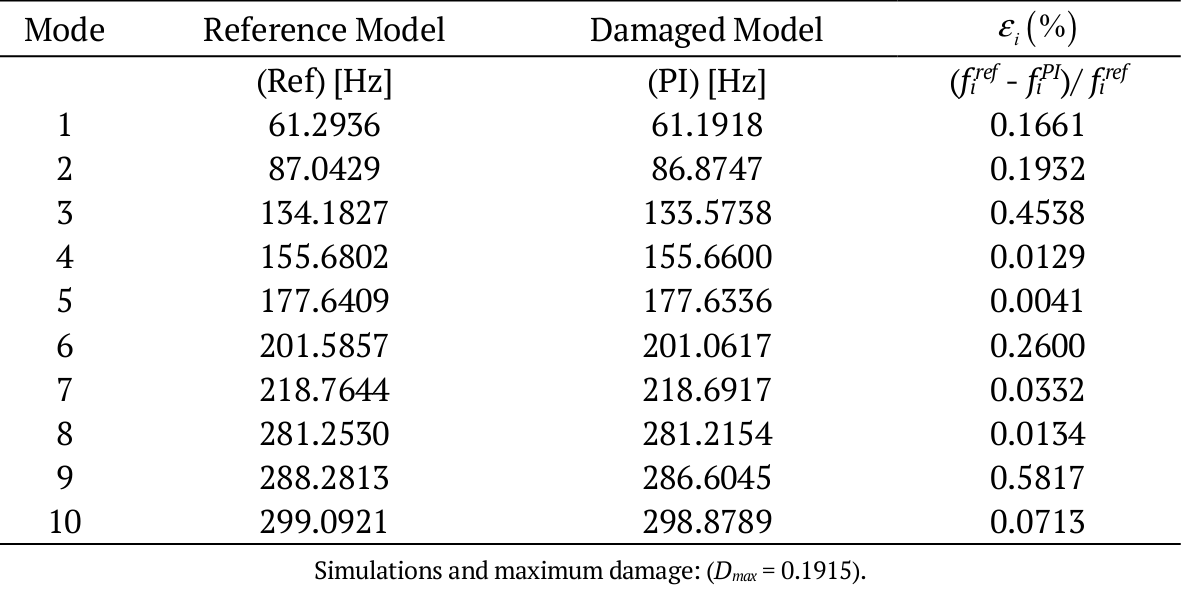
Table 2 also informs the natural frequencies of the damaged plate after (Ref) the impulsive load application.
The software Matlab@ has built-in functions (called ‘eig’) that compute generalized eigenvectors and eigenvalues given numerical values for M and K. The eigenvalues correspond to natural frequencies of vibration  (shown in Table 2), while the eigenvectors correspond to vibration modes ñ of system (illustrated in Figure 2).
For the second numerical application, an impulsive load F (t) is applied in the direction (Figure 1) on the plate center P (C/2, L/2), according to the Equation 12:
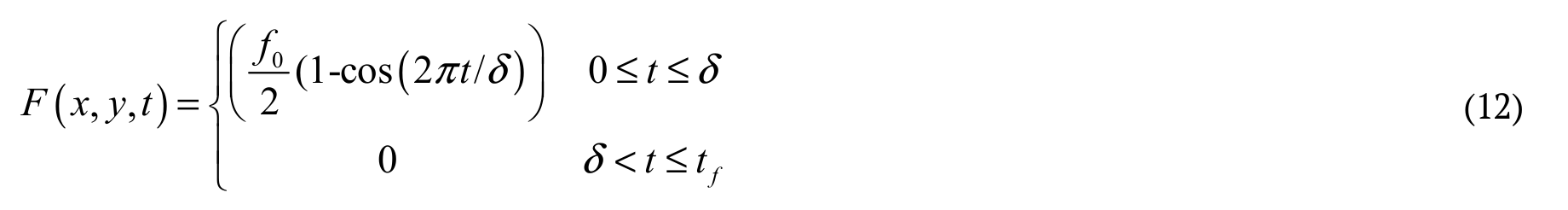 (12)
(12)where:
o is the applied excitement force amplitude over the structure, is the application period of F (t) and tfis the ending time of the force application. For this simulation, = 100 ms and tf = 250 ms, totaling 250 subdivided increments.
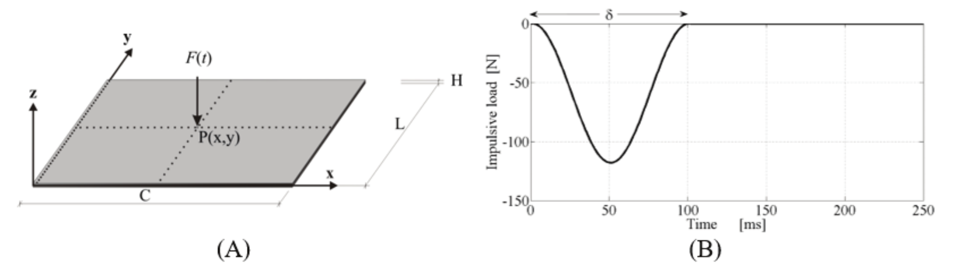
Figure 1.
Geometry of the considered laminated composite plate (A) and the applied impulsive load F (t) (B).
Mechanical properties of the laminated material, glass-epoxy.
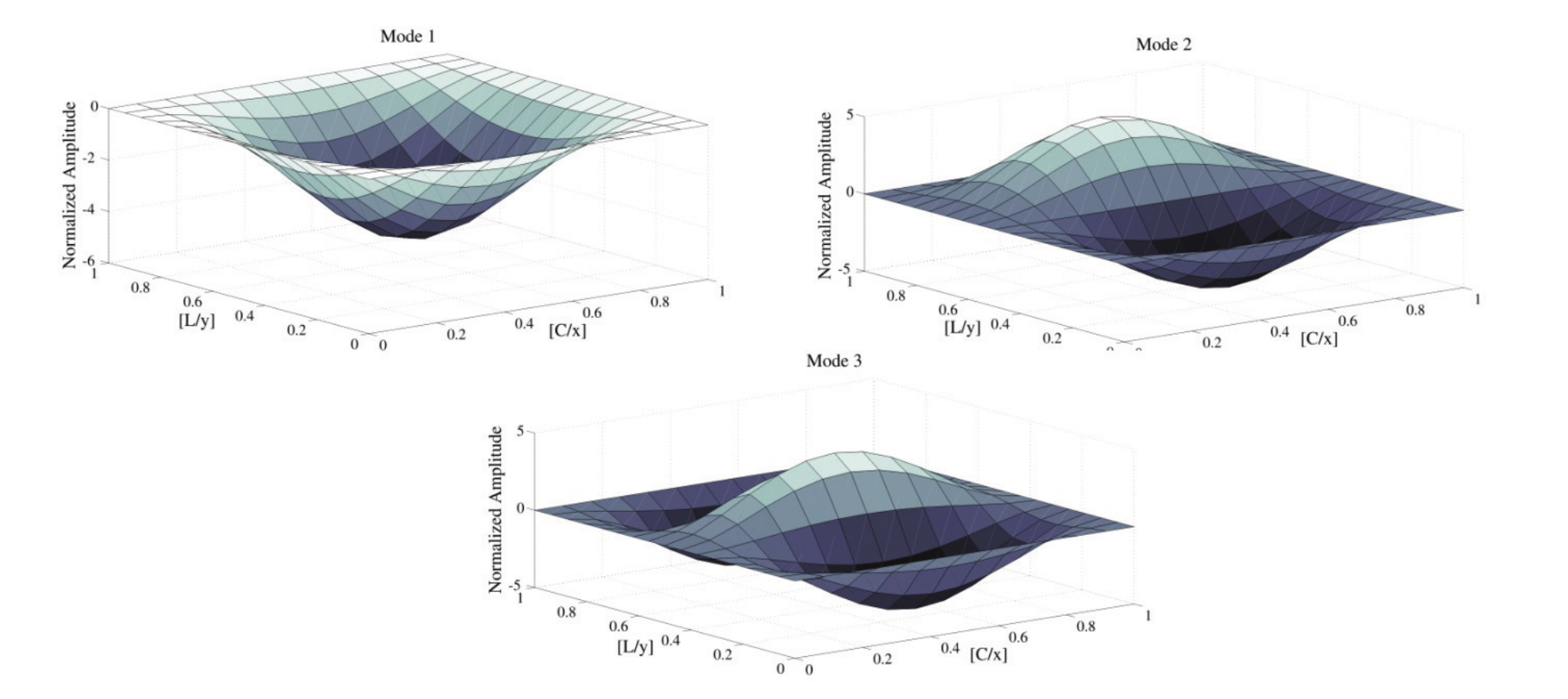
Figure 2.
Three first vibration modes of the laminated composite structure under a non-damaged condition.
Natural frequencies of the composite laminated plate under a non-damaged and damaged condition.
The function F (t) (Equation 12), applied to the laminated
composite plate according to the position and distribution depicted in Figure 1A
and B, respectively, represents a brief mechanical shock (). The maximum value of
such function occurs within a short time interval (/2), as shown in Figure 1B.
The function F (t) presents two phases, the
first consisting of a forced regime and corresponding to a time interval between
0 and , and the
second of a free regime that begins after and ceases with the ending time (tf) of
the load application on the structure with Function F (t). In the forced regime, the
inherent damping of the structure is not capable of dissipating the energy that
F (t) delivers to the system as well as reducing the maximum response
of the structure (displacement u, velocity  or acceleration ü) in an adequate time. In the free regime, the
structure will present the initial movement conditions (u,
or acceleration ü) in an adequate time. In the free regime, the
structure will present the initial movement conditions (u, and ü) established in the previous movement regime,
continuing, however, its vibratory movement.
and ü) established in the previous movement regime,
continuing, however, its vibratory movement.
Regarding the simulation, an impulsive load F (0.20, 0.15, t) is applied on the composite plate, having an amplitude o of 118 N.
Figure 3 A and B illustrates the damage scalar variable D distribution over the plate surface x-y, as well as its maximum value. That value is reached after the ending time of the impulsive load application (tf = 250 ms), and it is obtained for each of the average areas from the given composite structure. Since both external layers of the laminated composite plate presented identical distribution and values of the damage scalar variable D, it has been herein decided to illustrate in Figure 3A only the response of one of the two layers of the plate in study.
Figure 3 shows that the maximum value of the damage scalar variable (Dmax) occurs in the external layers of the laminated composite plate (Figure 3A). This is because both external layers have fibers oriented in the direction of the plate length, in other words, of the global axis x of the structure (according to the axes shown in Figure 1A) with null angle ( = 0o), and also because the fibers of the central layer are oriented in the direction of the global axis y of the composite plate, i.e. with a right angle ( = 90o) in relation to x. Thus, the orientation of fibers of both external layers of the laminated composite plate in study is more favorable to the openings of micro-cracks when compared to the central layer.
Figure 4 illustrates the development of the scalar damage variable D combined with the time deflection (displacement) from the closest Gauss point in relation to the first plate’s central point (from top to bottom).
Figure 4 shows that the value of the scalar damage variable rapidly increases until it reaches t = 50 ms and then remains constant until t = 227 ms, fluctuating again before going up to its maximum value (Dmax= 0.1915, illustrated by the dashed curve).
From Figure 4, it can be observed that the value of the scalar damage variable D (represented by the dashed line) progressively increases to about half the time of application of the impulsive load (/2), since the impulsive function F(t) also reaches its peak in /2 (Figure 1B). After the time interval /2, the value of D remains constant until approximately 227 ms (even with the decrease in the value of F(t), as depicted in Figure 1B), as the damage received by the laminated composite structure cannot be reverted, that is, the damaged state is kept in memory when the structure is subjected to a load ( Boubakar et al., 2002). After 227 ms, the magnitude of the variable D once again starts to increase until it reaches the peak (Dmax = 0.1915) in the ending time (tf) of the load application, i.e. in 250 ms. The increment with time in the scalar variable D can be explained by the increments in the internal stresses of the laminated composite plate during the free movement regime, since, without damping, these stresses keep increasing as the plate continuously moves. The maximum vertical displacement (solid line in Figure 4) experienced by the laminated plate ( máx = 0.024 m), however, occurs when the impulsive load reaches its maximum amplitude in /2. After this time, the magnitude of the vertical displacement progressively decreases until stabilising around 100 ms, in other words, in the phase of free movement regime of the laminated plate.
Table 2 summarizes the values from the first ten natural vibration frequencies of the composite structures, analyzed under a non-damaged stage (Ref) and under a damaged stage (PI).
It is possible to note from Table 2 that the natural frequency values decrease as the damage scalar variable D values increase within all simulations, which in turn indicates thickness losses in those composite structures by the time damage gets higher.
The damage fairly affects the shape of the first ten modes from the damaged structure, compared to when it is under a non-damaged stage. Besides, it leads only to a narrow divergence on the structure’s natural vibration frequencies, informed by the percent error (i) from Table 2, when comparing the structure under both structural stages according to the analyzed vibration mode ñ (ñ varying from 1 to 10 in the analyzed studies).
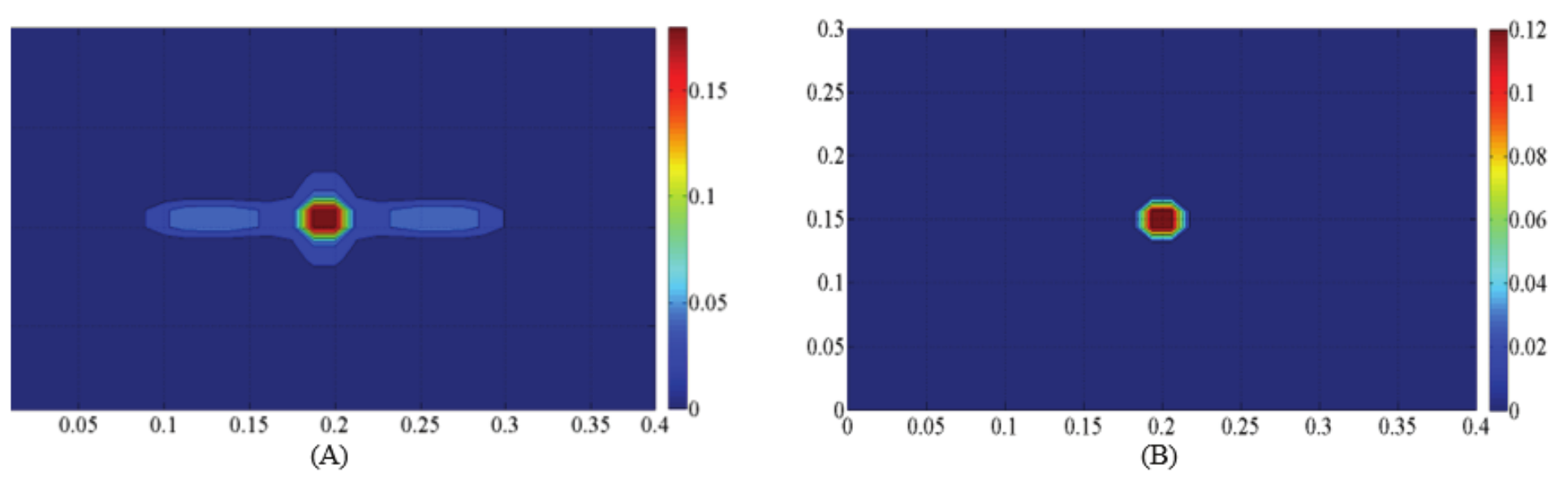
Figure 3.
The damage scalar variable D distribution over external layers (A), given Dmax= 0.1915, from its damaged composite plate and on its central (B), given Dmax = 0.1286.
Due to internal increment of stresses of the laminated composite plate subjected
to the impulsive load F(t), the magnitude
of the damage scalar variable D may or
may not change, in consonance with Equation 9 of the damage evolution law. If there
is an increment in the value of D, the
elastic properties of the layers of the composite plate will likewise change, in
other words, some of the constituent elements of matrix C1 (D) (Equation 4) may decrease in magnitude.
The decrease of the laminate elastic properties will consequently lead to the decrease
of the constituent elements of the matrix K (D) (dependent upon the damage scalar
variable D considering that the matrix
C1 (D) is incorporated into its
formulation) as well as to the decrease of the values of natural frequencies  of the damaged laminated composite
structure in comparison with the initial non-damaged structure.
of the damaged laminated composite
structure in comparison with the initial non-damaged structure.
The signal originated from the first vibration mode is directly decomposed through DWT and the Figure 5, as follows, illustrates the WC flat distribution along the plate surface (Figure 5A), obtained from the mother-wavelet sym7 (Symlet Wavelet of 7th order). The dynamic signals are gathered and processed via DWT considering a damaged stage (Figure 5B), non-damaged (Figure 5C) and also considering the signal difference under both stages (Figure 5D). It can be noted from all figures that the central area, to where the impulsive load was applied, presents the higher WC amplitude.
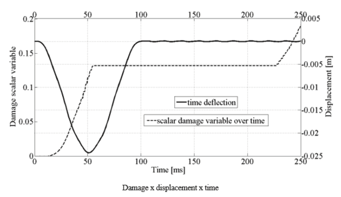
Figure 4.
Development of the scalar damage variable over time combined with the deflection, close to where the impulsive load was applied during simulation.
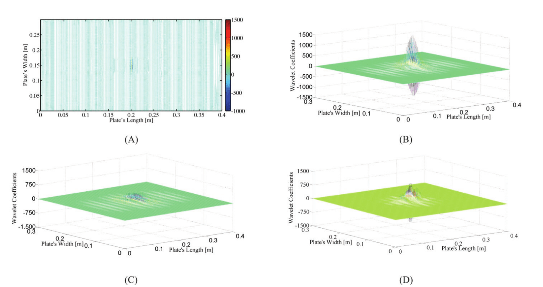
Figure 5.
Wavelet coefficients of the sym7 transform in a flat distribution along the plate surface (A) and spatially distributed for computing the plate’s dynamic signal considering: (B) a damaged stage, (C) a non-damaged stage, (D) the difference under both stages.
It is observed from Figure 5A and B that the sym7 transform was able to capture the damage on the central region, around where the impulsive load was applied. In those figures, the WC assume the highest value around the damaged central area and the difference between the originated signal from the plate under a damaged stage (Figure 5C) compared to when it was under a non-damaged stage (Figure 5D) is also capable of estimate the damage location, as it can be seen in Figure 5D.
Figure 5A illustrates top views of the same wavelet coefficient (WC) values depicted three-dimensionally in Figure 5B. The three-dimensional distribution of WCs along the plane of the laminated composite plate is obtained using the 1D-DWT wavelet transform, where a vector containing the modal signal of each of the Nx nodes of the finite elements oriented in the x direction of the composite plate is transformed through 1D-DWT. The set formed by all of the Ny vectors transformed through this 1D process and oriented in the y direction of the laminated composite plate enables the three-dimensional plotting of WCs along the x-y plane of the plate in study, as shown in Figure 5B, C, and D.
Conclusion
The present paper mathematically discusses the modeling of damaged laminated composite structures via FSDT-FEM and by incorporating a damage matrix mechanism.
SHM methodology proposed is able to detect and locate the damage in laminated composite structures, when they are subjected to mechanical shocks. Within SHM applications, the Discrete Wavelet Transform (DWT-1D) is adopted for spatially decomposing (along the plate surface) the vibration modes of damaged composite structures, even though in a 1D space. The wavelet coefficients that are obtained from this decomposition reach maximum values around the damaged area, which provides us with the approximate damage location.
It has been verified that the vibration mode pattern may accentuate the existent singularities in the wavelet coefficients, which allows the accurate damage detection proposed in this study.
Acknowledgements
To the National Council of Technological and Scientific Development (CNPq) for financially incentive the project: 482273/2012-7.
References
Addison, P. S. (2016). The illustrated wavelet transform handbook: introductory theory and applications in science, engineering, medicine and finance (2nd ed.). Boca Raton, FL: CRC Press.
Bathe, K. J. (2014). Finite element procedures in enginnering analysis (2nd ed.). Trenton, NJ: Prentice Hall.
Boubakar, M. L., Trivaudey, F., Perreux, D., & Vang, L. (2002). A meso-macro finite element modeling of laminate structures, part 1: time-independent behavior. Composite Structures, 58(2), 271-286. doi: 10.1016/S0263-8223(02)00049-1
Chang, C. C., & Chen, L.-W. (2004). Damage detection of a rectangular plate by spatial wavelet based approach. Applied Acoustic, 65(8), 819-832. doi: 10.1016/S0003-682X(04)00033-7
Faria, A. W., & Lima, A. M. G. (2014). Numerical formulation for the study of the damped composite structures using First and Higher-order Shear Deformation theories. Revista Internacional de Métodos Numéricos para Cálculo y Diseño en Ingeniería, 30(2), 77-84. doi: 10.1016/j.rimni.2012.11.004
Giurgiutiu, V., & Santoni-Bottai, G. (2011). Structural Health Monitoring of composite structures with piezoelectric-wafer active sensor. American Institute of Aeronautics and Astronautics Journal, 49(3), 565-581. doi: 10.2514/1.J050641
Kahya, V., & Turan, M. (2018). Vibration and stability analysis of functionally graded sandwich beams by a multi-layer finite element. Composites Part B, 146(1), 198-212. doi: 10.1016/j.compositesb.2018.04.011
Katunin, A., & Holewik, F. (2013). Crack identification in composite elements with non-linear geometry using spatial wavelet transform. Archives of Civil and Mechanical Engineering, 13(3), 287-296. doi: 10.1016/j.ymssp.2011.05.015
Limongelli, M. P., & Çelebi, M. (2019). Seismic Structural Health Monitoring: From Theory to Successful Applications. Switzerland, AG: Springer Nature.
Loutridis, S., Douka, E., Hadjileontiadis, L. J., & Trochidis, A. (2005). A two-dimensional wavelet transform for detection of cracks in plates. Engineering Structures, 27(9), 1327-1338. doi: 10.1016/j.engstruct.2005.03.006
Mahmoudi, S., Trivaudy, F., & Bouhaddi, N. (2015). Nonlinear dynamic response analysis of damage laminated composite structures. In M. Chouchane, T. Fakhfakh, H. B. Daly, N. Aifaoui, & F. Chaari (Eds.), Design and modeling of mechanical systems - II (p. 545-552). Hammamet, TN: Springer. doi: 10.1007/978-3-319-17527-0_54
Rhif, M., Abbes, A. B., Farah, I. R., Martínez, B., & Sang, Y. (2019). Wavelet Transform Application for/in Non-Stationary Time-Series Analysis: A Review. Applied Sciences, 9(7), 1345. doi: 10.3390/app9071345
Stark, H. G. (2005). Wavelets and signal processing an application-based introduction. New York, NY: Springer.
Talreja, R., & Singh, C. V. (2012). Damage and failure of composite materials. Cambridge, GB: Cambridge Universty Press.
Wang, Q., & Deng, X. (1999). Damage detection with spatial wavelets. International Journal of Solids and Structures, 36(23), 3443-3468. doi: 10.1016/S0020-7683(98)00152-8
Yan, Y. L., & Yam, L. H. (2002). Online detection of crack damage in composite plates using embedded piezoelectric actuators/sensors and wavelet analysis. Composite Structures, 58(1), 29-38. doi: 10.1016/S0263-8223(02)00043-0
Yang, J. M., Yang, Z. W., & Tseng, C. M. (2011). Damage detection in stiffened plates by wavelet transform. Journal of Nav Archit Oc Engng, 3(2), 126-135. doi: 10.2478/IJNAOE-2013-0055
Zhai, Y., Li, Y., & Liang, S. (2018). Free vibration analysis of five-layered composite sandwich plates with two-layered viscoelastic cores. Composite Structures, 200(15), 346-357. doi: 10.1016/j.compstruct.2018.05.082
Zhang, H., Shi, D., Zha, S., & Wang, Q. (2018). A simple first-order shear deformation theory for vibro-acoustic analysis of the laminated rectangular fluid-structure coupling syste. Composite Structures, 201(1), 647-663. doi: 10.1016/j.compstruct.2018.06.093
Zienkiewicz, O. C., Taylor, R. L., & Zhu, J. Z. (2013). The finite element method: its basis & fundamentals (7th ed.). Burlington, VT: Elsevier Press.
Author notes
albert.faria@uftm.edu.br
