Mechanical Engineering
Experimental research of capillary structure technologies for heat pipes
Experimental research of capillary structure technologies for heat pipes
Acta Scientiarum. Technology, vol. 42, e48189, 2020
Universidade Estadual de Maringá

Esta obra está bajo una Licencia Creative Commons Atribución 4.0 Internacional.
Recepción: 02 Junio 2019
Aprobación: 01 Noviembre 2019
Abstract: This paper presents an experimental study on three different capillary structure technologies of heat pipes for application in the thermal management of electronic packaging. The first capillary structure is that of axial grooves manufactured by wire electrical discharge machining (wire-EDM). The sintering process with copper powder produced the second heat pipe. Finally, a hybrid heat pipe was made by the combination of the two previous methods. The heat pipes were produced using copper tubes with an outer diameter of 9.45 mm and a length of 200 mm, and were tested horizontally at increasing heat loads varying from 5 to 35 W. The working fluid used was distilled water. The experimental results showed that all capillary structures for heat pipes worked successfully, so the studied manufacturing methods are suitable. Nonetheless, the hybrid heat pipe is the best, due to the lowest thermal resistance presented.
Keywords: heat pipe, axial grooves, wire-EDM, sintered metal powder, experimental.
Introduction
The thermal management of electronic packaging has become a key technique in many products (Alves & Altemani, 2011). Due to the innovation of modern electronic technology, the thermal systems miniaturization and the consequent rapid increase in the power density of advanced microprocessors and electronic components created a significant demand for achieving high heat dissipation rates (Nishida & Alves, 2014). In most cases, such high heat fluxes cannot be easily dissipated using existing cooling techniques, directly affecting the performance, cost, and reliability of devices (Wang, Yao, Shi, Wu, & Zhang, 2018). Heat pipes may be a good alternative for such applications (Ghajar & Darabi, 2014). According to Faghri (2014), heat pipes are highly effective passive devices for transmitting heat at high rates over considerable distances with small temperature decrease, flexibility, simple construction, and easy control with no external pumping power.
Heat pipes operate according to the following principle (Groll & Rösler, 1992): in the evaporator region, heat is transferred to the heat pipe, vaporizing the working fluid contained inside this region. Due to pressure and density differences, the vapor generated flows to the condenser, where transported heat is rejected to the cold source. In the heat rejection process, the vapor condenses, and the condensate returns to the evaporator, closing the cycle. The adiabatic region may have variable dimensions or be absent, is located between the evaporator and the condenser, and is insulated from the external environment (Santos, Vicente, Reis, Marquardt, & Alves, 2017). The working fluid returns from the condenser to the evaporator due to the capillary effect. A schematic diagram of the operating principle of heat pipes is presented in Figure 1(Santos, Krambeck, Santos, & Alves, 2014). Further details on heat pipe principles may be found in the works of Chi (1976), Peterson (1994), Reay, McGlen, and Kew (2014), and Faghri (2016).
A heat pipe consists essentially of three components: a casing, a working fluid, and a capillary structure (Vasiliev, 2008). The most common capillary structures are screens, sintered metals, and axial grooves (Krambeck, Nishida, Aguiar, Santos, & Alves, 2019). There are several types of groove cross-sections inside copper heat pipes, such as triangular, rectangular, trapezoidal, and inverse trapezoidal cross-sections, resulting in different heat transfer performances (Nishida, Krambeck, Santos, & Alves, 2020). How to produce ideal inner grooves is the primary problem with heat pipes (Wang, Tang, & Chen, 2009). Conventional manufacturing methods such as milling and broaching are expensive and may be difficult for small-scale production (Li, Xiao, Lian, Tang, & Zeng, 2008). Sintered metal wicks are manufactured by packing tiny metal particles between the inner heat pipe wall and a mandrel in powder form (Tang, Deng, Huang, Wan, & Lu, 2013). A hybrid structure improves the heat pipe performance by the conciliation of two common capillary structures (Paiva & Mantelli, 2015). Some studies available in the literature about different capillary structure technologies of heat pipes for application in the thermal management of electronic packaging are those by Obata, Fukushima, Alves, Bazani, and Paschoalini (2016), Gabsi, Maalej, and Zaghdoudi (2018), Grissa, Benselama, Lataoui, Bertin, and Jemni (2018), He et al. (2018), Han, Wang, and Liang (2018), Santos, Alves, Oliveira, and Bazzo (2018), Liu, Li, and Fan (2019), Tian, He, Liu, and Liu (2019), Velardo et al. (2019), He et al. (2020), Xiau et al. (2020), and Zhou, Li, Chen, Deng, and Gan (2020).
In this work, three capillary structure technologies of heat pipes for application in the thermal management of electronic packaging are experimentally studied, namely: a grooved heat pipe with semicircular axial grooves manufactured using wire electrical discharge machining (wire-EDM); a sintered heat pipe produced with spherical copper powder and a temporary mandrel, which placed powder in the annulus region; and a hybrid heat pipe made by the combination of the two previous methods, wire-EDM and sintering.
Material and methods
Experimental analysis
The methodology for the manufacturing (i.e., cleaning, assembly, tightness test, evacuation procedure, and filling with the working fluid), testing, and analysis of the heat pipes was developed based on the work by Alves, Krambeck, and Santos (2018).
Characteristics of developed heat pipes
The heat pipes were produced using copper tubes (ASTM B-75 Alloy 122) with an outer diameter of 9.45 and a length of 200 mm. The lengths of the heat pipe regions are of 80, 20, and 100 mm for the evaporator, adiabatic, and condensation regions, respectively. The working fluid used was distilled water, with filling ratios based on the best performance of each capillary structure. Table 1 presents the main characteristics of the heat pipes analyzed in this study.
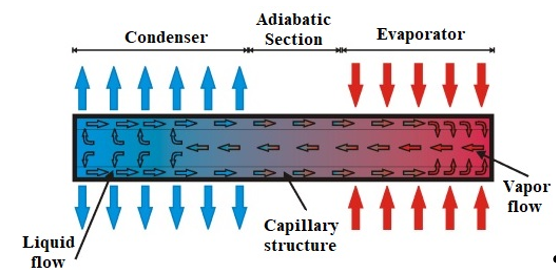
Figure 1.
Heat pipe sketch.
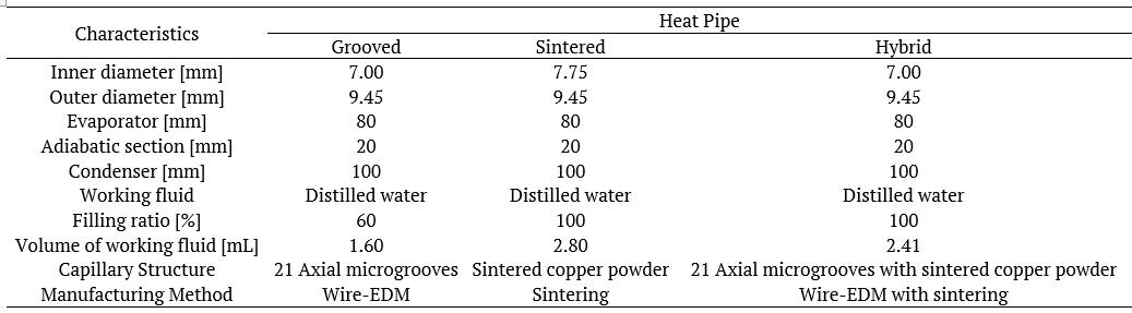
Table 1.
Main heat pipes characteristics.
The grooved heat pipe had 21 axial microgrooves made by wire electrical discharge machining (wire-EDM) using a FanucTM machine tool (model Robocut α-oic) with a FanucTM command (Series 180is-WB). A brass wire electrode (DIN 160) with a 0.2 mm diameter and 900 N mm–2 tensile was used. The parameter settings were an open circuit voltage at 41 V, a constant discharge current of 4.0 A, and a wire run-off speed of 0.3964 mm min.–1, achieving an accuracy of ± 6 µm. Deionized water dielectric fluid was responsible for concentrating the energy and cooling the wire and work piece. Figure 2 presents the axial microgroove details with an average diameter of 220 µm through a micro-scale image obtained by a Backscattered Electron Detector (BSD) on a Scanning Electron Microscope (SEM). Additional characteristics of grooved heat pipes are reported by Nishida et al. (2020).
The sintered heat pipe was produced by the sintering process with a plain tube, a monomodal copper powder, and a temporary mandrel. The average diameter of the copper powder particle was 33 μm. The apparatus used in the sintering process consisted of a controlled atmosphere horizontal tubular furnace (IntiTM FT-1200), a data acquisition system (AgilentTM 34970A with 20 channels), and a laptop (DellTM). The gas used in the atmosphere control was a mixture of 95 Argon and 5% Hydrogen. For the evaluation of the temperature inside the furnace, an Omega EngineeringTM type K thermocouple was used. The sintering occurred at a heating rate of 20°C min.–1, with a 15 min.–1 permanence at a temperature of 800°C and subsequent cooling by forced air convection. The manufactured porous structure has a thickness of 1.6 mm (Figure 3a). The micro-scale image of the sintered copper powder capillary structure is presented in Figure 3b. The wick porosity was obtained by Helium Pycnometry associated with physical characterization by the Archimedes method, showing that the total porosity of the capillary structure is 54.8%. Additional characteristics of the sintered heat pipe are reported by Krambeck, Bartmeyer, Fusão, Santos, and Alves (2019).
A grooved heat pipe with the same number of axial microgrooves made by the wire-EDM (i.e., 21) was sintered using the sintered heat pipe procedure presented before, obtaining the hybrid heat pipe. The temperature of the sintering process is approximately 75% of the melting temperature of copper, which avoids the sintering of the grooves. Due to the smaller inner diameter compared to the plain tube, the thickness of the sintered structure was approximately 1.3 mm. The porosity of the sintered capillary structure is 54.8%. Figure 4 presents the combination of microgrooves and sintered copper powder that compose the capillary structure.
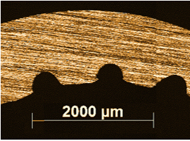
Figure 2.
Capillary structure: Grooved Heat Pipe – SEM micrograph.
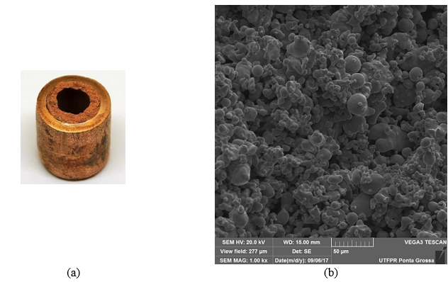
Figure 3.
Capillary structure: Sintered Heat Pipe.
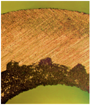
Figure 4.
Capillary structure: Hybrid Heat Pipe.
Description of the experimental apparatus
The essential apparatus used for the experimental tests, shown in Figure 5, is composed of a power supply unit (AgilentTM U8002A), a 20-channel data logger (AgilentTM 34970A), a laptop (DellTM), a universal holder, an uninterruptible power supply (NHSTM), and a fan (UltrarTM).
For the evaluation of the heat pipes’ thermal performance, type K thermocouples (Omega EngineeringTM) were used, having been fixed to the outer surface of heat pipes using a thermosensitive adhesive strip (KaptonTM). As shown in Figure 6, there were three thermocouples in the evaporators (Tevap,1, Tevap,2, and Tevap,3), one in the adiabatic sections (Tadiab), and four in the condensers (Tcond,1, Tcond,2, Tcond,3, and Tcond,4) of each heat pipe.
The evaporator’s heating system was conducted by power dissipation with a nickel-chromium alloy power strip resistor (Omega EngineeringTM) with a thickness of 0.1 and a width of 3.5 mm. To ensure that the heat generated by the Joule effect was transmitted to the evaporator, aeronautic thermal insulation (MTI PolyfabTM) and a polyethylene (3MTM) layer were installed in this region. A fiberglass tape (Omega EngineeringTM) was used in the adiabatic section as heat insulation between the holder and the heat pipe. The cooling system using forced air convection consisted of a fan in the condenser region.
Experimental procedure
To ensure the best results and repeatability of the experimental tests, the ambient temperature was maintained at 20.0 ± 1.0°C by the CarrierTM thermal conditioning system. The heat pipe was carefully fixed to the universal holder horizontally with a bracket at the adiabatic region. The fan was turned on, positioned correctly over the condenser region, and set at a speed of 5.0 m s–1 with a combined error of ± 0.2 m s–1. The average air speed was calculated following the handbook of the American Society of Heating, Refrigerating, and Air-Conditioning Engineers (Ashrae, 2017). The data acquisition system was turned on, and the temperatures were measured by the type K thermocouples. The power supply unit was turned on and adjusted to the desired dissipation power. The initial load was of 5 W and, after approximately 15 min., when the thermocouples showed stationary values. The load was incremented until the maximum average temperature of the heat pipe reached the critical temperature (150ºC), in which the materials could melt. Data were acquired every five seconds and recorded on the laptop by the AgilentTM Benchlink Data Logger 3 software. The experimental uncertainties are associated with the type K thermocouples, data logger, and power supply unit. The experimental temperature uncertainty is estimated to be of approximately 1.27°C, while the thermal load was around 1%. For determining the uncertainties, the error propagation method described by Holman (2011) was used.
Data reduction
The performance of the capillary structures was analyzed and compared with the operating temperature and thermal resistance. The operating temperature considered was from the adiabatic region. The total thermal resistance, Rth, of a heat pipe may be defined as the ratio of the total temperature drop across the device to the total heat transfer rate (Rohsenow, Hartnett, & Cho, 1998). The higher the thermal resistance is, the greater the difficulty in transporting heat from the system (Incropera, DeWitt, Bergman, & Lavine, 2006). The total thermal resistance may be calculated by Equation 1:
where q is the heat transfer capability of the device [W], and Tevap and Tcond are the average wall temperatures of the evaporator and the condenser, respectively [°C].
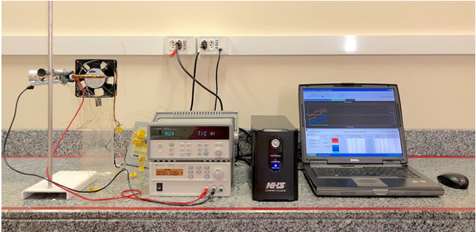
Figure 5.
Experimental apparatus.
![Thermocouple positions [mm].](../303265671056_gf9.png)
Figure 6.
Thermocouple positions [mm].
Results and discussion
The experimental results regarding the thermal behavior of the heat pipes with different capillary structure technologies operating in the horizontal position are presented here. The experimental tests were repeated thrice, and the errors calculated considering the difference between the mean values were less than 0.5°C. The tests were performed at heat loads increasing by 5 W, ranging from 5 to 35 W. Figure 7 shows the temperature distributions as a function of time for the heat pipes with different capillary structures (grooved, sintered, and hybrid). For all the technologies, the maximum dissipated power was 35 W. The hybrid and sintered heat pipes obtained more isothermal behaviors than the grooved heat pipe. The hybrid and sintered heat pipes start the operation at 5 and 10 W, respectively, when the adiabatic and condenser temperatures increase rapidly. They present virtually the same evaporator temperatures from the lowest heat load up to 35 W, after which the evaporator drying starts. It is possible to see the vapor front reaching the condenser as the heat load is increased. In the grooved heat pipe, the adiabatic temperature reaches a stable behavior at 20 W, and the separation of the Tcond,3 and Tcond,4 thermocouples at 30 and 35 W is probably due to the presence of non-condensable gases inside the grooved tube.
The operating temperature in function of the heat load is presented in Figure 8, rising with the increase of the heat load. In the grooved case, the heat pipe reaches the operating stability at 25 W. In turn, the sintered and hybrid heat pipes maintain their stability from the start. The sintered heat pipe can operate at a lower temperature than the grooved heat pipe. Also, the association of grooves and sintered powder improves the performance of the capillary structure, leading the hybrid heat pipe to operate at lower temperatures, including the adiabatic temperature.
Figure 9 illustrates the behavior of thermal resistance as a function of power dissipation considering the three different capillary structures. The heat pipes’ thermal resistances decrease with the rise in heat dissipation in the evaporator, as a result of the homogeneous thermal behavior of the capillary structures. The grooved heat pipe only works with heat conduction at 5 and 10 W, after which boiling starts and the thermal resistance drops. The sintered and hybrid heat pipes present a decrease of the thermal resistance ever since the first heat load on. This occurs because the sintered structure creates nucleation sites that anticipate the liquid boiling, even in lower heat loads.
All the heat pipes worked successfully, given that the capillary structures provided to them the operation at higher loads and lower thermal resistance. Thus, the results were satisfactory since the intention of these tests was to evaluate the efficiency of the capillary structure manufacturing methods. Therefore, the studied manufacturing methods are deemed suitable. Also, the hybrid structure is the best capillary structure technology considering the lowest thermal resistance and a slightly lower operating temperature than the other heat pipes.
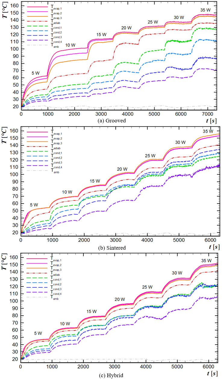
Figure 7.
Heat pipe temperatures over time for different heat loads.
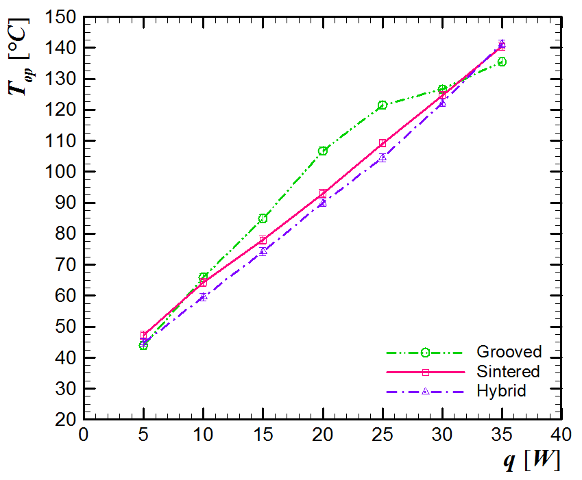
Figure 8.
Operation temperature versus heat load of different capillary structure technologies.
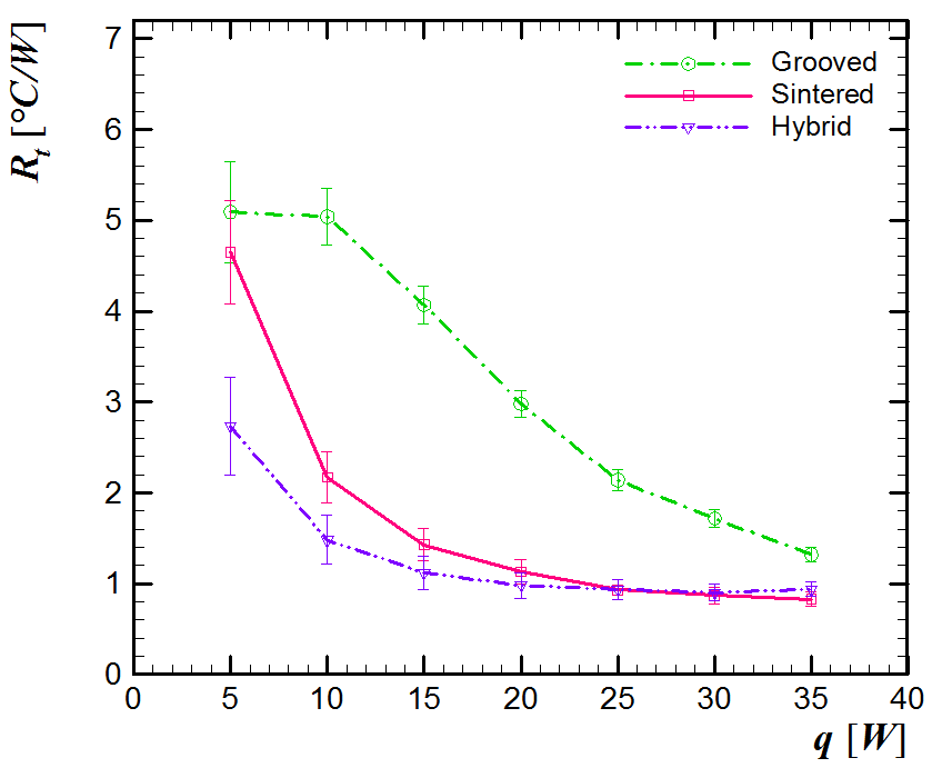
Figure 9.
Thermal resistance versus heat load of different capillary structure technologies.
Conclusion
This paper presented an experimental study of three heat pipes with different capillary structure technologies for application to the thermal management of electronic packaging. The studied heat pipes were that with axial grooves, the sintered metal powder pipe, and the hybrid. The heat pipes were tested horizontally using distilled water as the working fluid. As a result of the study, it was found that all the heat pipes worked successfully, so the used manufacturing methods are suitable. Nonetheless, the hybrid heat pipe is the best, due to the lowest thermal resistance presented.
Acknowledgements
The authors would like to express their gratitude to the Coordenação de Aperfeiçoamento de Pessoal de Nível Superior (Capes) and the Conselho Nacional de Desenvolvimento Científico e Tecnológico (CNPq), as well as the Office of Research and Post-Graduation (PROPPG), the Directory of Research and Post-Graduation (DIRPPG), the Graduate Program in Mechanical Engineering (PPGEM), and the Academic Mechanics Department (DAMEC) of the UTFPR, Campus of Ponta Grossa.
References
Alves, T.A., & Altemani, C. A. C. (2011). Conjugate cooling of a discrete heater in laminar channel flow. Journal of the Brazilian Society of Mechanical Sciences and Engineering, 33(3), 278-286. doi: 10.1590/S1678-58782011000300003
Alves, T. A., Krambeck, L., & Santos, P. H. D. (2018). Heat pipe and thermosyphon for thermal management of thermoelectric cooling. In P. Aranguren (Ed.), Bringing thermoelectricity into reality (p. 353-373). London, UK: IntechOpen.
American Society of Heating, Refrigerating and Air-Conditioning Engineers [Ashrae]. (2017). ASHRAE handbook: fundamentals. New York, NY: Ashrae.
Chi, S. W. (1976). Heat pipe theory and practice: a sourcebook. Washington, DC: Hemisphere Publishing Corporation.
Faghri, A. (2014). Heat pipes: review, opportunities and challenges. Frontiers in Heat Pipes, 5(1), 1-48. doi: 10.5098/fhp.5.1
Faghri, A. (2016). Heat pipe science and technology (2nd ed.). Kanpur, IND: Global Digital Press.
Gabsi, I., Maalej, S., & Zaghdoudi, M. C. (2018). Thermal performance modeling of loop heat pipes with flat evaporator for electronics cooling. Microelectronics Reliability, 84, 37-47. doi: 10.1016/j.microrel.2018.02.023
Ghajar, M., & Darabi, J. (2014). Evaporative heat transfer analysis of a micro loop heat pipe with rectangular grooves. International Journal of Thermal Sciences, 79, 51-59. doi: 10.1016/j.ijthermalsci.2013.12.014
Grissa, K., Benselama, A. M., Lataoui, Z., Bertin, Y., & Jemni, A. (2018). Investigations of the thermal performance of a cylindrical wicked heat pipe. International Journal of Energy Research, 42(9), 3048-3058. doi: 10.1002/er.3973
Groll, M., & Rösler, S. (1992). Operation principles and performance of heat pipes and closed two-phase thermosyphons. Journal of Non-Equilibrium Thermodynamics, 17(2), 91-152. doi: 10.1515/jnet.1992.17.2.91
Han, X., Wang, Y., & Liang, Q. (2018). Investigation of the thermal performance of a novel flat heat pipe sink with multiple heat sources. International Communications in Heat and Mass Transfer, 94, 71-76. doi: 10.1016/j.icheatmasstransfer.2018.03.017
He, S., Zhao, J., Liu, Z.-C., Tian, W., Yang, J.-G., & Liu, W. (2018). Experimental investigation of loop heat pipe with a large squared evaporator for cooling electronics. Applied Thermal Engineering, 144, 383-391. doi: 10.1016/j.applthermaleng.2018.08.075
He, S., Zhou, P., Ma, Z., Deng, W., Zhang, H., Chi, Z., ... Liu, Z. (2020). Experimental study on transient performance of the loop heat pipe with a pouring porous wick. Applied Thermal Engineering, 164, 114450. doi: 10.1016/j.applthermaleng.2019.114450
Holman, J. P. (2011). Experimental methods for engineers (8th ed.). New York, NY: McGraw-Hill.
Incropera, F. P., DeWitt, D. P., Bergman, T. L., & Lavine, A. S. (2006). Fundamentals of heat and mass transfer (6th ed). Trenton, NJ: John Wiley & Sons.
Krambeck, L., Bartmeyer, G. A., Fusão, D., Santos, P. H. D., & Alves, T. A. (2019). Permeability of a capillary structure of sintered copper powder used in heat pipes. International Journal of Advanced Engineering Research and Science, 6(2), 199-202. doi: 10.22161/ijaers.6.2.26
Krambeck, L., Nishida, F. B., Aguiar, V. M., Santos, P. H. D., & Alves, T. A. (2019). Thermal performance evaluation of different passive devices for electronics cooling. Thermal Science, 23(2B), 1151-1160. doi: 10.2298/TSCI170610300K
Li, Y., Xiao, H., Lian, B., Tang, Y., & Zeng, Z.-X. (2008). Forming method of axial micro grooves inside copper heat pipe. Transactions of Nonferrous Metals Society of China, 18(5), 1229-1233. doi: 10.1016/S1003-6326(08)60209-5
Liu, C., Li, Q., & Fan, D. (2019). Fabrication and performance evaluation of flexible flat heat pipes for the thermal control of deployable structure. International Journal of Heat and Mass Transfer, 144, 118661. doi: 10.1016/j.ijheatmasstransfer.2019.118661
Nishida, F. B., & Alves, T. A. (2014). Conjugate cooling of 3D protruding heaters with laminar flow in a rectangular channel. International Review of Mechanical Engineering, 8(2), 360-369. doi: 10.15866/ireme.v8i2.462
Nishida, F. B., Krambeck, L., Santos, P. H. D., & Alves, T. A. (2020). Experimental investigation of heat pipe thermal performance with microgrooves fabricated by wire electrical discharge machining (wire-EDM). Thermal Science, 24(2A), 701-711. doi: 10.2298/TSCI180227206B
Obata, D. H. S., Fukushima, J. C., Alves, T. A., Bazani, M. A., & Paschoalini, A. T. (2016). Experimental study of a Cu-Mo alloy vapor chamber. MATEC Web of Conference, 39, 02001. doi: 10.1051/matecconf/20163902001
Paiva, K. V., & Mantelli, M. B. H. (2015). Wire-plate and sintered hybrid heat pipes: model and experiments. International Journal of Thermal Sciences, 93, 36-51. doi: 10.1016/j.ijthermalsci.2015.01.037
Peterson, G. P. (1994). An introduction to heat pipes: modeling, testing, and applications. Toronto, CA: John Wiley & Sons.
Reay, D. A., McGlen, R. J., & Kew, P. A. (2014). Heat pipe: theory, design and applications (6th ed.). Amsterdam, NL: Butterworth-Heinemann.
Rohsenow, W. M., Hartnett, J. P., & Cho, Y. I. (1998). Handbook of heat transfer (3rd ed.). New York, NY: McGraw-Hill.
Santos, P. H. D., Alves, T. A., Oliveira, A. A. M., & Bazzo, E. (2018). Analysis of a flat capillary evaporator with a bi-layered porous wick. Thermal Science, OnLine-First(00), 240-240. doi: 10.2298/TSCI180419240S
Santos, P. H. D., Krambeck, L., Santos, D. L. F., & Alves, T. A. (2014). Analysis of a stainless steel heat pipe based on operation limits. International Review of Mechanical Engineering, 8(3), 599-608. doi: 10.15866/ireme.v8i3.902
Santos, P. H. D., Vicente, K. A. T., Reis, L. S., Marquardt, L. S., & Alves, T. A. (2017). Modeling and experimental tests of a copper thermosyphon. Acta Scientiarum. Technology, 39(1), 59-68. doi: 10.4025/actascitechnol.v39i1.28957
Tang, Y., Deng, D., Huang, G., Wan, Z., & Lu, L. (2013). Effect of fabrication parameters on capillary performance of composite wicks for two-phase heat transfer devices. Energy Conversion and Management, 66, 66-76. doi: 10.1016/j.enconman.2012.09.027
Tian, W., He, S., Liu, Z., & Liu, W. (2019). Experimental investigation of a miniature loop heat pipe with eccentric evaporator for cooling electronics. Applied Thermal Engineering, 159, 113982. doi: 10.1016/j.applthermaleng.2019.113982
Vasiliev, L. L. (2008). Micro and miniature heat pipes - electronic component coolers. Applied Thermal Engineering, 28(4), 266-273. doi: 10.1016/j.applthermaleng.2006.02.023
Velardo, J., Date, A., Singh, R., Nihill, J., Date, A., Phan, T. L., & Takahashi, M. (2019). Experimental investigation of a vapour chamber heat spreader with hybrid wick structure. International Journal of Thermal Sciences, 140, 28-35. doi: 10.1016/j.ijthermalsci.2019.02.009
Wang, C., Yao, F., Shi, J., Wu, L., & Zhang, M. (2018). Visualization study on thermo-hydrodynamic behaviors of a flat two-phase thermosyphon. Energies, 11(9), 2295. doi: 10.3390/en11092295
Wang, X., Tang, Y., & Chen, P. (2009). Investigation into performance of a heat pipe with micro grooves fabricated by extrusion-ploughing process. Energy Conversion and Management, 50(5), 1384-1388. doi: 10.1016/j.enconman.2009.01.009
Xiau, B., Deng, W., Ma, Z., He, S., He, L., Li, X., ... Liu, Z. (2020). Experimental investigation of loop heat pipe with a large squared evaporator for multi-heat sources cooling. Renewable Energy, 147(Part 1), 239-248. doi: 10.1016/j.renene.2019.08.142
Zhou, W., Li, Y., Chen, Z., Deng, L., & Gan, Y. (2020). Ultra-thin flattened heat pipe with a novel band-shape spiral woven mesh wick for cooling smartphones. International Journal of Heat and Mass Transfer, 146, 118792. doi: 10.1016/j.ijheatmasstransfer.2019.118792
Notas de autor
antonini@utfpr.edu.br