A tribute to Pere Santanach
Weld kinematics of syn-rift salt during basement-involved extension and subsequent inversion: Results from analog models
Weld kinematics of syn-rift salt during basement-involved extension and subsequent inversion: Results from analog models
Geologica Acta: an international earth science journal, vol. 16, no. Esp.4, pp. 391-410, 2018
Universitat de Barcelona

This work is licensed under Creative Commons Attribution-ShareAlike 4.0 International.
Received: 01 February 2018
Accepted: 01 May 2018
Published: 01 November 2018
Funding
Funding source: GEOMODELS Research Institute and the Grup de Geodinàmicai Anàlisi de Conques
Contract number: 2014SGR-467
Abstract: Scaled analog models based on extensional basins with synrift salt show how basement topography exerts a control factor on weld kinematics during the extension and inversion phases. In the case of basement-involved extension, syn-rift salt thickness differences may lead to variable degrees of extensional decoupling between basement topography and overburden, which in turn have a strong impact on the development of salt structures. With ongoing extension and after welding, the basin kinematics evolves toward a coupled deformation style. The basin architecture of our experimental results record the halokinetic activity related to growing diapirs and the timing of weld formation during extension. Moreover, the structures that result from any subsequent inversion of these basins strongly depends on the inherited welds and salt structures. While those basins are uplifted, the main contractional deformation during inversion is absorbed by the pre-existing salt structures, whose are squeezed developing secondary welds that often evolve into thrust welds. The analysis of our analog models shows that shortening of diapirs is favored by: i) basement topography changes that induce reactivation of primary welds as thrust welds; ii) reactivation of the salt unit as a contractional detachment and iii) synkinematic sedimentation during basin inversion. Finally, in this article, we also compare two natural examples from the southern North Sea that highlight deformation patterns very similar to those observed in our analog models.
Keywords: Extension and inversion, Salt tectonics, Syn-rift salt, Analog modeling, outhern N, Southern North Sea.
INTRODUCTION
The timing of salt deposition, pre-, syn-, or post-kinematic, during the evolution of the salt-bearing rift basins is one of the main factors controlling their structural style (Jackson and Vendeville, 1994; Rowan, 2014). In fact, the development of salt structures in this scenario is influenced by salt thickness differences or by its lateral continuity, which in turn is controlled by basement topography prior to salt deposition (Fig. 1A). Although, the most important thickness differences occur with syn-rift salt, the presence of previous topographic irregularities can also favor salt thickness differences in pre-rift salt. The origin of these subsalt salt irregularities could be diverse but may be related to the irregular erosion of basement rocks or to the different slip of rift faults (Dooley et al., 2017; Ferrer et al., 2017).
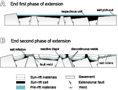
Figure 1.
Conceptual model on the structural style of syn-rift salt basins. A) During the first extensional phase syn-rift salt accumulates in grabens and half-grabens so salt thickness varies and B) salt rollers, reactive diapirs, passive diapirs and fault welds form in the syn-kinematic overburden; modified from Jackson and Hudec, 2017.
If these rift basins are subsequently inverted, the syn-kinematic sedimentation, the inherited structure and the continuity of the salt layer or its welded equivalent, strongly influences the propagation of contractional deformation. Salt structures are inherently weaker than other parts of the basin; because of this weakness diapirs react sensitively to contraction long before any surrounding rocks (Letouzey et al., 1995, Letouzey and Sherkati, 2004; Rowan and Vendeville, 2006; Callot et al., 2007; Callot et al., 2012; Dooley et al., 2015). Initial shortening is visibly focused on diapirs which displace salt upwards and squeeze the diapir whereas surrounding areas deform by lateral compaction (Vendeville and Nilsen, 1995; Nilsen et al., 1995; Cramez and Jackson, 2000; Rowan et al., 2000, 2004).
While much has been written on rift basins with pre-rift salt (e.g.Koyi and Petersen, 1993, Nalpas et al., 1995; Vendeville et al., 1995; Brun and Nalpas, 1996; Withjack and Callaway, 2000; Dooley et al., 2005; Soto et al., 2007; Burliga et al., 2012; Ferrer et al., 2016), there is little published about the role of synrift salt during extension and subsequent inversion. Koyi et al. (1993) used a centrifuge to study the influence of basement faults on diapirism in sedimentary basins. Their models showed that, when syn-rift salt only occupied half-grabens and the overburden covered the entire model the development of salt structures is constrained by the major faults. Jackson and Vendeville (1994) documented a close link between the onset of diapirism and regional extension considering different world’ salt basins with syn-rift salt, which in turn influence the distribution of resulting diapirs. Del Ventisette et al. (2005) explored the influence of positive inversion on diapirism in previously extended basins with syn-rift salt. Using an experimental approach based on the western Central Graben (North Sea), Dooley et al. (2005) investigated the 3D geometries and kinematics of deformation in the overburden above intersecting basement fault systems that were separated by a salt layer. In this work they indicate that this intersecting fault set generates complex 3D flap structures in the overburden that localize diapiric activity. Ferrer et al. (2014, 2016) used a rigid footwall to simulate different basement fault geometries with pre- and syn-rift salt to understand the main factors controlling the overburden deformation and salt tectonics during extension and inversion. Our investigation agrees with their regarding the presence of a salt layer acting as an effective decoupling unit, and the effect of basement geometry controlling the location of salt structures. However, our work differs from Dooley et al. (2005) and Ferrer et al. (2014) because they did not apply inversion (or if so, very few). Finally, despite the experiments of Ferrer et al. (2016) considered the effect of inversion, the small amount of previous extension applied did not allow the development of diapirs.
The present work expands the experimental program and the methodological analysis of Roma et al. (2018) in order to provide insights into welding kinematics in basins with syn-rift salt during both extension and inversion phases. Despite some authors pointing that salt thinned by welding during extension in nature become less effective to act as a detachment, our experimental results show that primary welds can be forced to reactivate as thrust welds by basement topography variation during inversion. Moreover, our models demonstrate that syn-inversion sedimentation clearly favors the development of vertical secondary welds, decapitated diapirs or even thrust welds. Those features are well recognized at the north-eastern edge of the Broad Fourteens Basin (BFB) and at the northern edge of the Dutch Central Graben (DCG), in the southern North Sea.
EXPERIMENTAL METHODOLOGY
This contribution is part of a wider experimental program including 5 different experiments (Table 1) and they complement the recent work of Roma et al. (2018) which characterized the kinematics of salt-detached ramp-syncline basins during extension and subsequent inversion. Here, we have selected three end-member experiments to illustrate the evolution of salt structures during extension and inversion, paying special attention to the role of syn-kinematic sedimentation.
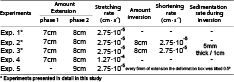
Summary table showing the main characteristics of the experimental program
Experimental design and material properties
Our analog models were designed using the same experimental setup as Yamada and McClay (2003a, b) and subsequently improved by Ferrer et al. (2016). Analog models were carried out in a 63cm-long, 30cm-wide and 35cm-deep, glass-sided deformation box (Fig. 2A). A rigid wooden footwall block with double ramp-flat faults constrained the footwall geometry. Above the almost flat section of the footwall, a metal plate was fixed to form the breakaway of the extensional fault system (Fig. 2A). Between the rigid footwall and this metal plate, and covering the entire footwall, a flexible (but not stretchable) plastic sheet was attached to the fixed end walls (Fig. 2A). It acted as a major detachment during both extension and inversion. Lengthening or shortening were transmitted to the hanging wall sand pack with a motor-driven worm screw attached to the footwall block (Fig. 2A). The extensional and contractional displacement rates of the moving footwall remained constant during the experimental program (2.75x10⁻⁵cm s-1). These deformations and syn-kinematic sedimentation rates were selected after two testing models in order to favor polymer flow, such as the salt in nature.

Figure 2.
Synoptic sketches showing the experimental procedure with the terminology used in the description of the models (modified after Roma et al., 2018). A) pre-deformation configuration, B) structural pattern at the end of the first extensional phase (after 7cm of stretching), C) experimental configuration at the end of the second extensional phase (after an additional 8cm of stretching), red and white layers represent syn-kinematic sedimentation, D) configuration at the end of the inversion (after 7cm of shortening) and E) structural pattern at the end of the inversion (after 7cm of shortening), green and white layers represent syn-inversion sedimentation.
The materials used in the experimental program are summarized in Table 2. Dry silica sand with an average grain size of 250μm simulates the brittle sedimentary rocks of the upper crust and a polydimethylsiloxane polymer (PDMS) is the analog for salt (Weijermars, 1986). Silica sand has a Mohr-Coulomb behavior at moderate values of normal stress (McClay, 1990). The mechanical properties of poured sand were measured using a ring shear tester at the Fault Dynamics Analog Modeling Laboratory at Royal Holloway University of London, resulting in an angle of internal friction of 34.6º, a bulk density of 1500kg m-3and a low apparent cohesive strength of 55Pa. In contrast, the polymer (PDMS) has a near-perfect Newtonian fluid behavior when deformed at a laboratory strain rate of 1.83x104cm s-1 (Dell’Ertole and Schellart, 2013). It has an effective viscosity of 1.6x10⁴Pas and a density of 972kg m-3 at 20ºC. The coefficient of sliding friction between the basal plastic sheet and the sand pack was 0.37 (Huiqi et al., 1992; Konstantinovskaia and Malavieille, 2005).
As shown in Table 2, the experiments were dynamically scaled (e.g. Hubbert, 1937; Schellart, 2000) in such a way that 1cm in the model is equivalent to ~1km in nature (see McClay, 1990, for the details of the scaling).
Scaled parameters used in the experimental program
Experimental procedure
The pre-kinematic sand pack was formed by pouring 3mm-thick, white and colored sand horizontal layers covering the footwall block and the plastic sheet, with a total thickness of 9.3cm above the horizontal basal detachment (Fig. 2A). The models were initially extended by 7cm at a displacement rate of 1.6x10⁻³cm s-1. After this first phase of extension, the resultant hangingwall ramp-anticline and the ramp-syncline basin were filled by a polymer layer of variable thickness ranging from 0cm (at salt pinch-out) to 3.7cm (at the deepest depocenter) (Fig. 2B). Prior to the second phase of extension the polymer was overlaid by a 1cm-thick sand layer. Subsequent stretching was applied at a rate of 2.75x10⁻⁵cm s-1with up to 8cm of total extension (15cm, considering both phases) (Fig. 2C). During this stage, syn-kinematic sediments were added for every 5mm of extension keeping a constant regional datum equal to the one existing at the beginning of the second extensional phase (Fig. 2C). Syn-kinematic sedimentation increased the differential load between basin depocenters and their edges enhancing polymer flow and localizing diapirism. Once the polymer reached the surface of the experiment through passive diapirs, the regional datum was raised by 3mm for each new syn-kinematic layer. Overhangs formed by polymer extrusion onto the model’s surface were manually removed to simulate salt dissolution in nature, before adding a syn-kinematic layer (Rowan and Vendeville, 2006).
While Experiment 1 ended after the second extensional phase, Experiments 2 and 3 were subsequently inverted by 8cm (Fig. 2D, E) at a shortening rate of 2.75x10⁻⁵cm s-1 until recover of the second extensional phase. Experiment 2 did not consider syn-kinematic sedimentation during the inversion stage (Fig. 2D). However, in Experiment 3, green, white and black syn-inversion sand layers were added after each 1cm of shortening raising the regional datum to 5mm-thick (Fig. 2E).
Completed models were covered by a thick post-kinematic sand layer to preserve the final topography and inhibit any undesired polymer movement. They were subsequently gelled and serially sectioned into 3mm-thick vertical slices.
Modeling limitations
Although the use of rigid blocks to force the geometry of normal faults has been widely employed in analog modeling (McClay, 1989, 1995; Buchanan and McCLay, 1991; Roure and Colleta, 1996; Yamada and McCLay, 2003a, b), the main disadvantage of this technique is the inability of rigid footwalls to deform (McClay, 1995; Bonini et al., 2012). This fact prevents the formation of basement-involved footwall structures as shortcuts, or horses, as occurs in nature (e.g.McClay, 1989, 1995; Nalpas et al., 1995; Eisenstadt and Sims, 2005). Despite this limitation, we combined the rigid footwall and a brittle pre-salt sand pack to impose topographic variations during deformation, and both were considered to be the basement. We focus the analysis of our experimental results on how these basement topographic variations affect salt kinematics and the evolution of welds during both extension and inversion.
Data capture, analysis and visualization techniques
In addition to the foregoing limitations, the presence of polymer enhances friction and produces smearing against the glass sidewalls. This masks the structures’ evolution through the glass due to the edge effects. For this reason, the evolution of our experiments during both extension and inversion was documented using top-view time-lapsed photographs taken every 60 seconds with high-resolution digital cameras. To analyze the along-strike variations of structures, the vertical sections sliced at the end of the experiments were also recorded using digital cameras. In order to avoid the edge effects, a 5cm-wide section was neglected along each side of the experiments during their analyses.
To constrain the structural analysis, we used the final serial cross-sections of each experiment to build Voxel models in image-processing software, which allow the creation of virtual strike and depth slices (Dooley et al., 2009; Ferrer et al., 2016, 2017). In addition, following the methodology proposed by Hammerstein et al. (2014) we also converted the cross-section photographs into SEG-Y format to be loaded into seismic interpretation software to create a seismic volume (Fig. 3A). This allowed an accurate interpretation of each of the horizons and faults, paying special attention to the top and bottom of the polymer layer to characterize the along-strike variation of salt structures (Fig. 3B). The 3D seismic interpretation was carried out with Petrel (Schlumberger) and the maps were built using Gocad (Paradigm).
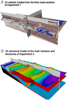
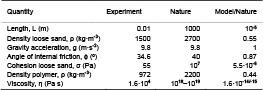
Figure 3.
A) 3D seismic cube obtained from the final cross-sections of Experiment 1 and B) the 3D structural model resulting from the interpretation of the 3D seismic of Experiment 2.
MODELING RESULTS
In this section, we summarize the main results of the three end-member experiments (Table 1). We begin with the experiment affected by extension (Experiment 1) and then, with the two experiments that were also subjected to inversion (Experiments 2 and 3). In the first case, we illustrate how the combination of a major basement fault and a syn-rift salt layer with significant thickness differences affects salt migration and the rise of salt structures during extension. In contrast, the second set of experiments depicts the inherited configuration (salt and basement faults) as being contractionally reactivated and rejuvenated during inversion, in addition to the role of syn-kinematic sedimentation during inversion.
Extension above a ramp-flat-ramp basement fault with syn-rift salt
The hanging wall geometry at the end of the first extensional phase was characterized by two major depocenters (landward rollover and basement ramp-syncline, Fig. 2B) flanking a structural high (basement ramp-anticline, Fig. 2B). The space created by the extensional motion of the rigid footwall was carefully filled with polymer simulating syn-kinematic salt and preserving the topography of the pre-kinematic sequence. Thus, the salt exhibits important variations in thickness, being thicker in the two depocenters, constant above the horizontal panels, and pinching out against the rigid footwall upper flat. These thickness differences simulate different sub-basins with syn-rift salt or post-rift salt units filling the topography generated during the rift in nature.
With ongoing extension during the second phase, two different deformation styles characterized the evolution of the overburden above the upper and the lower basement fault ramps. These two styles are clearly controlled by the salt thickness differences inherited from the first extensional phase (e.g. Jackson and Vendeville, 1994; Jackson et al., 1994; Vendeville et al., 1995). So, the thin salt layer above the breakaway fault favored strong coupling between basement and overburden extension, with the early development of an extensional forced fold that rapidly evolved into an extensional fault-propagation fold (Figs. 4A; 5A). This led to the upwards propagation of the breakaway basement fault through the salt into the overburden, which constrained the development of a landward rollover at the hanging wall block (Fig. 5A, B). As extension progressed, the growth of this rollover forced the salt evacuation towards the rollover hinge, thus arching the overburden above the pre-extension regional datum by inflation (Fig. 4A). Extension also produced the early downdip translation of the overburden over the gently-dipping upper flat panel of the rigid block. Consequently, different basinwards-dipping salt-detached listric faults controlled the rise of asymmetric reactive diapirs and salt rollers close to the salt pinch-out (Figs. 4A; 5A, B).
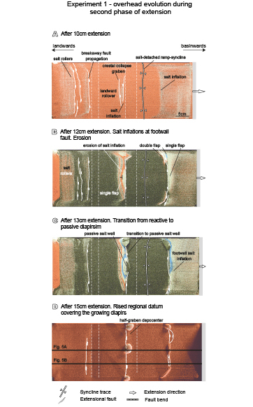
Figure 4.
Interpreted top-view photographs showing the extensional evolution of Experiment 1 (illumination is from the right) after A) 10cm, B) 12cm, C) 13cm and D) 15cm of extension. Continuous black lines in Figure 4D correspond to the cross-section locations of Figure 5.
In contrast, above the lower ramp, where the salt layer was thicker, the overburden deformation was initially decoupled from basement extension. In this case, most of the subsidence related to the basement ramp-syncline was filled by salt that triggered the development of two drape monoclines bounding a salt-detached ramp-syncline in the overburden (Roma et al., 2018). Figure 5C illustrates a structural map of Experiment 1 at the top of the salt unit that defines the main features detached on salt, whereas the map of Figure 5D illustrates the basement structure. Note the differences in structural styles between both horizons, which mean that the salt layer acts as a markedly effective decoupling layer during extension (e.g.Koyi et al., 1993; Vendeville et al., 1995; Stewartand Clark, 1999; Withjack and Callaway, 2000). As extension progressed, the interplay between basement extension and lithostatic load produced by syn-kinematic sedimentation forced salt migration from the sub-basin depocenters towards their edges where salt-inflated ridges developed (e.g. Kehle, 1988; Koyi et al.,1993; Hudec and Jackson, 2007; Ferrer et al., 2014) (Fig. 6A, B). After 10cm of extension, overburden stretching in the inflated areas produced crestal collapse grabens (Fig. 6C) which evolved into a half graben as extension progressed (Fig. 6D). The basinward-dipping normal faults of these half grabens controlled the growth of reactive walls (Fig. 6D) in the central part of the experiment where both the extensional fault slip and the salt flow were maximum. The geometry of the basement ramp-anticline enhanced salt migration towards the inflated area located above it in comparison with the ridge at the basinward edge of the basin (Fig. 4A, B). This fact is clearly visible in the top-view photographs of Experiment 1 after 12cm of extension (Fig. 4B). Here, the erosion related to salt inflation is higher in the footwall of the normal fault located above the basement ramp-anticline than at the basinward edge of the basin (erosion of pre-kinematic white and blue sand layers in Fig. 4B). This different timing of salt extrusion is caused by the progressive erosion of any topographic high formed by salt inflation during syn-kinematic sedimentation, which enhanced salt rising and the formation of single or double vertical flaps of pre-kinematic sand. These flaps flank the reactive wall above the basement ramp-anticline (Ge et al., 1995). After 13cm of extension, the intense erosion at the edges of the salt-detached ramp-syncline basin favors salt piercement and extrusion (Figs. 4C; 6E). From this moment the regional datum was progressively raised to preserve the passive diapirs. This maximum fault slip at the central part of the experiments generate along-strike transition of both salt walls, from the passive salt wall in the central part of the model (Figs. 5A; 6E.2) to the reactive salt wall towards the glass-side (Figs. 5B; 6E.1).
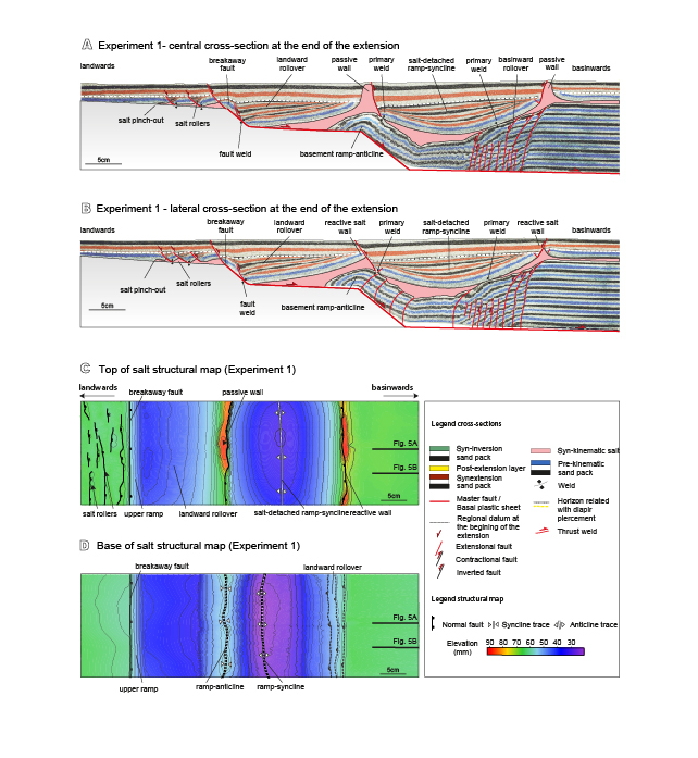
Figure 5.
Interpreted cross-sections and structural maps of Experiment 1 showing the different style of salt structures along-strike: A) cross-section at the central part of the experiment at the end of the extension, B) lateral cross-section at the end of extension, C) structural map of the suprasalt structures and D) structural map of the subsalt structures (contours in mm). Reddish color indicates a structural high and blue, structural lows. Structures marked with a continuous line correspond to the faults affecting the overburden whereas dashed structures are those affecting the basement. See Figure 4D for cross-section location.
During extension, the source layer was progressively stretched, thinned and finally depleted with the development of primary welds (Jackson and Cramez, 1989) (Fig. 5A, B). Different weld types developed in our experiments associated with the salt rollers (primary welds), below the landwards rollover at the hanging wall of the upper ramp (fault weld) and at both limbs of the salt-detached ramp-syncline (primary welds). The formation of these welds, especially at the upper ramp and below the salt-detached ramp-syncline favored coupling between overburden and basement deformation (Fig. 5A, B).
Inversion of a ramp-flat-ramp basement fault with syn-rift salt
The analog models described in this section were partially inverted (Bally, 1984). This inversion recovered the 8cm of stretching, which occurred during the second extensional phase. The inherited extensional architecture, the location of salt structures and the presence of primary welds dramatically controlled the evolution of the contractional structures during this episode. Independent of the syn-inversion sedimentation (Experiment 3), shortening produced the contractional reactivation of the main basement faults, the uplift of the two basins (the landward rollover and the salt-detached ramp-syncline), and the squeezing of salt structures that increased salt flow and extrusion (Fig. 7A).
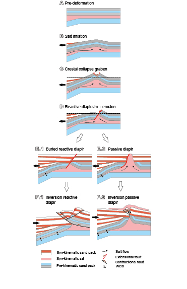
Figure 6.
Synoptic model showing the different stages of salt structures evolution at the edges of the salt-detached ramp-syncline basin: A) Pre-deformational stage, B) at the beginning of extension with salt inflated areas fed by the flow from below the basin towards its edges, C) as extension progressed, the collapse grabens developed at the crest of these anticlines, D) evolving into basinward-dipping normal faults like a reactive diapir. From this point the reactive diapir could be buried (E.1) or could have evolved to a passive diapir (E.2). With ongoing inversion, an early pop-up structure flanked by opposite-verging thrusts developed above the buried reactive diapir (F.1). As shortening progressed the right flank of this diapir was thrusted basinward. In contrast, the passive diapir was squeezed, developing a secondary weld (F.2).
As soon as inversion began, the inherited weak salt walls at both edges of the salt-detached ramp-syncline reactivated their growth. After 1cm of inversion (Fig. 7C.1), the partial closure of the stems drives a significant increase of upwards salt flow rates producing lateral extrusion and small overhangs on the model surface. During this initial stage, the reactive sectors of the salt walls were contractionally rejuvenated by squeezing, developing anticlines or thrust anticlines on top of them (Fig. 7C.1, C.2). The new topography forces the extruding salt flow, thereby developing salt sheets. At this point the breakaway fault was partly reactivated and propagated upwards into the syn-extensional cover as a reverse fault (Fig. 7C.1, C.2). This arched, folded and uplifted the landwards rollover and developed an asymmetric anticline that verged landward (Fig. 7C.1, C.2).
With the ongoing inversion, salt extrusion continued and part of the coalesced salt sheets was amalgamated developing symmetric allosutures (Dooley et al., 2012) (Fig. 7C.3). The different contractional strength along-strike in the salt walls results in curved thrusts (thrust salient at reactive salt walls) that form reentrants towards the squeezed passive walls (Fig. 7C.1, C.4) (Dooley et al., 2009). Top-view photographs clearly illustrate how much of the salt walls have an elongated shape, thus indicating partial closure of the stems with associated secondary welds (Fig. 7C.4). The development of secondary welds is not coeval at both syncline-edging salt walls and it depends on the salt available at the source layer, the presence of primary welds, their reactivation and the width of the pre-contractional salt body. The surface that was primarily welded at the end of the extension at both syncline limbs is larger above the basinward rollover (Fig. 5A, B). This clearly limited the volume of salt available to be expulsed during shortening, and therefore, favors a faster secondary welding of the salt wall above the basinward rollover hinge (Fig. 7A). Secondary welding is also enhanced by the reactivation of primary welds as thrust welds that cause the uplift of the salt-detachment ramp-syncline (Fig. 7A).
After 7–8cm of shortening, the uplift of the landwards rollover produced an arrowhead or harpoon structure (Badley et al., 1989) with a crestal collapse graben (Fig. 7C.3, C.4). Part of this shortening propagated above the upper flat panel of the major fault using the salt as a contractional detachment. As a result, a faulted detachment fold nucleated at the salt pinch-out (Fig. 7A, B, C.4). The salt-detached ramp-syncline was also uplifted with a clockwise rotation pushed by the widening of the basement ramp-anticline as inversion progressed (Fig. 7A, B). At this point, the contractional deformation at the secondary welds developed small thrusts nucleated at the upper part of salt pedestals (Figs. 6F.2; 7A). In contrast, asymmetric anticlines developed along-strike on the hanging wall of the thrusts that nucleated at the apex of the reactive salt wall (Figs. 6F.1; 7B). The complexity of the fault pattern of these anticlines depends on the geometry of the inherited salt wall at the beginning of the inversion.
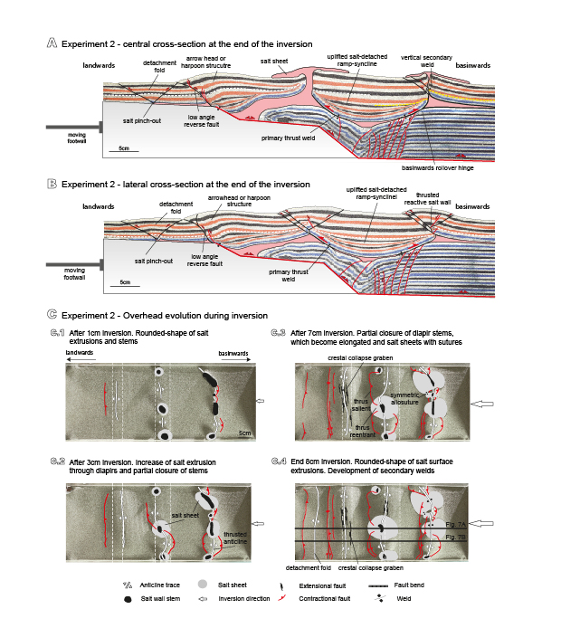
Figure 7.
Interpreted cross-sections of Experiment 2 showing the main structural elements and the different style of salt structures along-strike: A) central cross-section at the end of the inversion, B) lateral cross-section at the end of the inversion. C) Interpreted top-view photographs showing the evolution of Experiment 2 during inversion without syn-inversion sedimentation after 1cm (C.1), 3cm (C.2), 7cm (C.3) and 8cm (C.4) of inversion. Continuous white lines in Figure 7C.4 correspond to the cross-sections locations of Figure 7A, B. In all the photographs illumination is from the right and surfaces in shadow are dipping to the left. See Figure 5 for legend.
Inversion of a ramp-flat-ramp basement fault with syn-rift salt and syn-inversion sedimentation
At the end of extension Experiment 3 was covered by a 5mm-thick post-extensional layer made of yellow sand (Fig. 8A, B). This layer buried the different salt structures at the salt-detached ramp-syncline edges. The evolution of the experiment with syn-inversion sedimentation (Experiment 3) during an early shortening episode is similar to the one previously described for Experiment 2. After 1cm of inversion, the buried passive diapirs were contractionally rejuvenated as active diapirs. Shortening reactivated the upwards salt migration, arching and uplifting the thin diapirs roof above their surroundings. A linear thrust developed after 2cm of shortening by the inversion of the breakaway fault (Fig. 8C). Thrust salients and reentrants also developed by the squeezing of the two salt walls at both salt-detached ramp-syncline edges (Fig. 8C.1). The stem of the central passive wall gradually lengthened by squeezing, stretching its plan section orthogonally to the shortening direction (Fig. 8C.1, C.2).
As inversion progressed, between 3–5cm of shortening, the salt extrusion rate significantly decreased. This fact is related to the squeezing of diapir stems and the development of secondary welds, isolating the feeder from the source layer (Fig. 8A). During mild shortening (4.5–5cm), the salt-detached ramp-syncline is intensely uplifted by the strong basement topography variations; this was forced by the hanging wall accommodation to the rigid footwall geometry. This produces diapir stem closure and concentrates deformation at the two curved thrusts (with opposite vergence at both basin edges). With between 5–6cm of shortening, secondary welds evolve into thrust welds. The salt walls’ pinch-off above the basement ramp-anticline create an allochthonous teardrop that is decapitated by thrust welds (Fig. 8C.2). Short-cuts nucleated into the thrust weld and then propagated contractional deformation into the overburden. These short cuts produced a landward offset of the contractional deformation front and the thrust reentrant became inactive (Fig. 8C.3). At this point, the gradual thickness increase of the syn-inversion package hinders the contractional propagation of the breakaway fault being finally buried as a blinded thrust (Fig. 8A, B, C.3). In contrast to Experiment 2, the shortening propagation at the footwall of this thrust and the reactivation of the salt pinch-out is totally inhibited by the thick syn-kinematic unit (Fig. 8A, B, C.3).
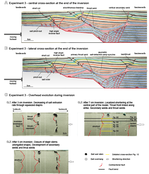
Figure 8.
Interpreted cross-sections of the Experiment 3 showing the main structural elements and the different style of salt structures along-strike: A) central cross-section at the end of the inversion, B) lateral cross-section at the end of the inversion, C) interpreted top-view photographs showing the evolution of Experiment 3 (with syn-inversion sedimentation) after 3cm (C.1), 5cm (C.2) and 7cm (C.3) of inversion. Continuous black lines in Figure 8C.3 correspond to the cross-section locations of Figure 8A, B. Yellow lines correspond to the different detailed cross-sections of Figure 12. In all the photographs illumination is from the right and surfaces in shadow are dipping to the left. See Figure 5 for legend.
After intense shortening (7–8cm), the only active contractional structure is the thrust related to the salt wall above the basement ramp-anticline (Fig. 8C.3). The allochthonous teardrop located at the hanging wall of the thrust weld is displaced by up to 4cm from its original position above its pedestal (Fig. 8A). In contrast, the syn-inversion sedimentation buried the salt wall at the opposite basin edge (Fig. 8A, C.3). It was partially squeezed while developing vertical secondary welds and faulted pop-ups above the diapir (Fig. 8A, B). The welding kinematic differences between the two edges of the salt-detached ramp-syncline basin forced the clockwise rotation of the basin at the hanging wall of the thrust weld (Fig. 8A, B).
DISCUSSION
Welding kinematics
The subsidence of the salt-detached ramp-syncline basin during extension drives salt flow from the basin depocenter towards its edges where salt inflated anticlines evolve into salt walls. While this occurs, the overburden gradually approaches the underlying basement by thinning the source layer until they eventually come into contact, developing a primary weld. However, unlike what happens when the base of the salt unit is horizontal, the existence of basement topography constraints welding kinematics.
Syn-kinematic infill layers show a syncline basin with different sedimentary architectures at both edges (Fig. 5A, B). Whereas these layers progressively onlap against the syncline limb located above the basement ramp-anticline, they form a wedge with different internal unconformities at the other syncline limb (Fig. 5A, B). This architecture completely changes with the formation of the first primary weld at the basinward rollover. From here, the salt-detached ramp-syncline basin subsides asymmetrically towards the unwelded limb, expelling salt landward to the adjacent passive diapir. This produces a counter-clockwise rotation of the salt-detached ramp-syncline basin that modifies the basin fill architecture to a half-graben and slightly folds the unconformity (white dashed line in Fig. 5A, B). This rotation, favored by salt expulsion, also widens the primary weld at the basinward rollover hinge (Fig. 5A). Sinking ceases with the development of the second primary weld at the landward limb of the basement syncline. Despite the length of this new weld, it is shorter than the previous one (Fig. 9A), but it is enough to interrupt diapir feeding. This is demonstrated by a significant reduction of the salt extrusion rate (Fig. 4D).
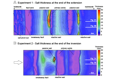
Figure 9.
A) Thickness maps of salt at the end of the extensional phase for Experiment 1 and B) at the end of the inversion for Experiment 2. Purple colors indicate the areas where salt was depleted thus developing primary welds, whereas yellowish colors correspond to the salt walls with maximum salt thicknesses. White lines correspond to the cross-section locations of Figures 5A, B and 7A, B.
At this point the overburden is stuck to the basement. Further extension then increases the width of the basement ramp-syncline, thus dragging the overburden and widening the passive diapir (cryptic extension).
Primary welds at the end of the extension strongly contrast with those observed at the end of the inversion (Fig. 7A, B). The comparison of salt thickness maps between Experiments 1 and 2 (Fig. 9) clearly depicts that: i) the length of the primary welds below the salt-detached ramp-syncline progressively increase during shortening and ii) it is reduced for the fault weld related to the breakaway fault. Inversion implies important basement topographic variations, such as the gradual uplift of the basin. This uplift is associated with a width reduction of the basement ramp-syncline (compare this to the width of the basement syncline between Figs. 5A–7A; 5B–7B). Width reduction implies an asymmetric uplift of the salt-detachment ramp-syncline basin pushed by basement topographic variations above the lower ramp (Fig. 7A). These processes lead to a change in the weld kinematics. That is, pre-existing primary welds are reactivated as thrust welds (Roma et al., 2018) involving shear along their surfaces. Both the uplift and the progressive primary welds’ contractional reactivation favors the squeezing of passive diapirs located at the basin edges. These structures could be totally squeezed hence developing secondary vertical welds (Fig. 7A).
Reactivation of sub-horizontal primary welds as thrust welds during later contraction is common in fold-and-thrust belts of convergent or passive margins with pre-existing diapirs and welded minibasins (e.g. Basque Pyrenees, La Popa Basin, Flinder Ranges, Angola Margin) (Brun and Fort, 2004; Rowan and Vendeville, 2006; Hudec and Jackson, 2007). Gottschalk et al. (2004, figs. 7 and 11) and Rowan and Vendeville (2006, fig. 9) show some restorations that illustrate sub-horizontal primary welds serving as thrust welds. Nevertheless, only scarce examples of dipping primary welds reactivated as thrust welds have been provided in the literature. These types of structures should develop in inverted rift basins with syn-rift salt or post-rift salt filling pre-existing relief in which the source layer can have an original dip. This is typical at the margins of the rift where topographic relief is more important or is located between sub-basins. Similar structures have been found at the north-eastern edge of the BFB and at the northern edge of the DCG (Fig.10). These salt-bearing rift basins developed during Jurassic–Early Cretaceous times and were later inverted during the Late Cretaceous–Early Tertiary (De Jager, 2003). In both cases, Zechstein salt acted as a decoupling layer during basement-involved rifting. The differential loads created by syn-rift sedimentation triggered salt migration towards the edges of the basins (NE edge of the BFB and at both edges in the DCG) feeding the growth of diapirs above the major faults (Fig. 10). The depletion of the source layer, especially above the basin-bounding faults, probably resulted in a discontinuous primary weld that dipped towards the basin with a steeped geometry that is controlled by the offset of basement faults and the topographic relief.
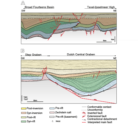
Figure 10.
Natural examples of inverted salt basins. A) Line drawing of the SW-NE seismic profile in the Dutch offshore at the transition from the offshore extension of the Texel-Ijsselmeer High to the Broad Fourteens Basin (southern North Sea) (modified from De Jager, 2003) and B) line drawing of the regional SW-NE profile through salt structures across the eastern part of the Dutch Central Graben (southern North Sea - Netherlands). Seismic image obtained from Virtual Seismic Atlas (VSA) by Fugro.
Despite the fact that the degree of inversion was stronger in the BFB than in the DCG (compare Fig. 10A, B), due to BFB strike at high angles to the direction of compression (Letouzey et al., 1995) salt structures show similar kinematic evolutions. The inversion of the northern sector of the BFB resulted in folding, uplift and erosion (Nalpas et al., 1995). Zechstein salt inhibited the basement fault propagation into the overburden (Dronkers and Mrozek, 1991) and favored the development of a striking thrust weld detached on this salt (De Jager, 2003) probably from an inherited squeezed salt structure. The hanging wall of this thrust weld, formed by Upper Jurassic–Lower Cretaceous rocks (basin infill), was carried onto the footwall of the major inverted extensional fault thus bounding the rift basin (Fig. 10A). This major fault disconnects the salt unit during the extension; note how the inversion of the basin perfectly fits with the harpoon structure that developed in our experiment (Fig. 7A, B). In contrast, the southern margin of the DCG (Fig. 10B) shows a salt-detached ramp-syncline basin that is flanked by collapsed salt diapirs, mainly developed by a major kinked basement fault. Just as it occurred in our experiments, the basinward dipping salt remnants and their equivalent primary welds located at the edge of the basin above the major basement fault probably served as thrust welds during the early stages of inversion. However, we have not had the opportunity to study recently reprocessed seismic data from the area, so this hypothesis is for the moment, merely speculative.
How does syn-inversion sedimentation affect regional structure and salt tectonics?
The comparison between Experiments 2 and 3 (Figs. 7A–8A; 7B–8B) shows that in addition to the structural architecture inherited from the extensional episode, the syn-kinematic sedimentation plays a key role in strain localization and the evolution of salt structures during inversion. Furthermore, it is also critical to the timing of contractional structures.
In both models, the contractional reactivation of the breakaway fault forced an asymmetrical uplift of the landward rollover. This formed a harpoon structure due to the propagation of this fault into the cover in a coupled deformation style. However, as documented for fold-and-thrust belts, syn-inversion sedimentation controls the dip and the shape of the reverse fault that propagates into the cover (Baby et al., 1995; Storti and McClay, 1995; Barrier et al., 2013). While Experiment 2 shows a low angle curved reverse fault flattening upwards (Fig.7A, B), this fault is planar and has a high angle in Experiment 3, which had syn-kinematic sedimentation (Fig. 8A, B). Another important point is how syn-kinematic sedimentation favors the back-rotation of the salt-detached ramp-syncline basin during uplift (Fig. 8A, B) (McClay, 1989, 1995; Buchanan and McClay, 1991; Bonini et al., 2012; Ferrer et al., 2016). In a similar manner to the experiments of Ferrer et al. (2016), who used a rigid footwall to constrain the geometry of different faults -and considering pre-extension salt- in our models the salt acted as a decoupling layer that transferred contractional deformation landward above the upper flat panel. This décollement was extremely efficient in the experiment without syn-inversion sedimentation where a detachment fold was flanked by two reverse faults that were developed at the salt pinch-out (Fig. 11A). In contrast, it was not effective in the experiments with syn-inversion sedimentation where contractional deformation was absorbed by a footwall short-cut and did not propagate landward (Fig. 11B). Similar examples have been described in fault-and-thrust belts where, despite the existence of a décollement, syn-kinematic sedimentation can inhibit the outwards propagation of the deformation front into the foreland (Bonini, 2001; Bonini et al., 2012).
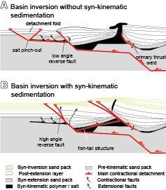
Figure 11.
Conceptual sketch on the effect of syn-kinematic sedimentation during inversion: A) basin inversion without syn-kinematic sedimentation, where the contractional deformation propagates towards the salt pinch-out and it is mainly absorbed by the frontal thrust related to the harpoon structure and B) basin inversion with syn-kinematic sedimentation where the thrust front has a high angle and the main contractional deformation is absorbed by the pre-existing salt wall also favored by the salt layer transferring deformation towards the salt wall, while developing a fish-tail.
Our experimental results also demonstrate how the thickening of the syn-inversion unit directly controls where and how deformation localizes and therefore the timing of the contractional kinematics. Figure 8C illustrates how the growth of contractional structures is constrained by syn-kinematic sedimentation. During early inversion the deformation was preferentially absorbed by the upward propagation of the fault breakaway as a reverse fault and by the central salt wall (Fig. 8C.1). Incremental syn-kinematic sedimentation buried the reverse fault related to the breakaway fault propagation and the contractional deformation switched backwards to the central salt wall. This was favored by the salt layer that acts as a shear zone that transfers the deformation basinward developing a fish-tail structure (Letouzey et al., 1995) (Fig. 11B). Similar structures have been interpreted in contractional scenarios with different detachment layers (Pichot and Nalpas, 2009). The central salt wall absorbed the main contractional deformation and it was squeezed shut. Squeezing forms thrusts and folds, which trend away in map view due to the 3D strain compatibility differences between salt and adjacent rocks (Fig. 8C.1, C.2). These differences constrain the development of reverse faults where the inherited salt wall was reactive (Fig. 12A, E) and that progressively curve towards the diapirs, creating thrust reentrants where the inherited salt wall was passive (Fig. 12B, C, D). If the inversion continues after secondary welding (Fig. 12C), the diapir separates from their original pedestal (decapitated diapir) (Fig. 12B) or develops a thrust weld (Fig. 12C, D). This change in the structural style is so critical to the thrust’s geometry that it is progressively smoothed until it develops a straight thrust front (Fig. 8C.3). This evolution is consistent with the models presented by Rowan et al. (1999) or Dooley et al. (2009). Figure 8A, B illustrate how the growth of the frontal short-cut ends after the sedimentation of the second green layer. This is practically coeval to the age of the pop-up structure above the squeezed diapir at the basinward rollover.
Despite the effect of the syn-kinematic sedimentation during inversion, we should not rule out the influence of different sedimentation rates as well as the erosion, on the evolution of these tectonic processes. These two factors tend to favour or inhibit the landward propagation of contractional deformation (Storti and McClay, 1995; Graveleau et al., 2012) as well as the squeezing and extrusion rates of salt structures.
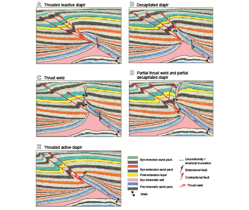
Figure 12.
Serial detailed cross-sections of Experiment 3 showing how inversion increases towards the weak diapir inherited from the extensional phase where shortening was focused. Note the along-strike variation of the inverted salt wall above the basement ramp-anticline. A) Thrusts nucleating at the apex of a pre-existing reactive diapir, B) squeezed passive diapir with a vertical secondary weld subsequently decapitated, C) squeezed passive diapir with a vertical secondary weld that evolves to a thrust weld when shortening continues, D) partial thrust weld and decapitated diapir and E) thrusts nucleating at the apex of a pre-existing reactive diapir. The inherited structure (reactive or passive diapir) and syn-inversion sedimentation are the main factors controlling the structural evolution during inversion. See Figure 8C.3 for location.
CONCLUSIONS
We have used analog models to investigate the influence of welding kinematics on the deformation patterns associated with extended and inverted basins with syn-rift salt and how basement topography variations impact it. Our work shows that while salt distribution and basement topography constrain welding kinematics during extension, the inherited structures, the continuity of the salt layer or its welded equivalent, and the syn-inversion sedimentation is what drive the welds’ evolution during late inversion. In this sense, the main conclusions of this research are:
-
i) The interaction of basement fault offsets and syn- rift salt thickness variations between different sub- basins determines coupled/decoupled deformation during extension. The thin salt layer favors the upwards propagation of basement faults into the overburden in a coupled deformation. When this occurs, the continuity of the source layer is interrupted and can halt the growth of salt structures. In contrast, a thick salt layer favors the development of a salt-detached ramp-syncline basin partially decoupled from basement fabrics.
ii) Salt thickness also has an impact on the salt structures’ style during extension. While salt rollers dipping basinward develop where the salt is thinner, salt walls develop at the edges of the salt-detached ramp-syncline as salt thickness increases.
iii) Primary welding enhances basement and overburden coupling in areas with thin and thick salt layers. The interplay between basement topography, salt thinning by expulsion and sedimentation load as extension progresses, constrains the complex welding kinematics.
The asymmetrical sinking of the salt-detached basin infers the timing of welding. Welding kinematics can be also noticed by basin rotations and by the depocenter’s trajectory variations in syn-extension sediments.
iv) The pre-existing structure (basement faults, salt continuity and the presence of primary welds) plays a key role during inversion. Changes to basement topography during inversion control welding kinematics, where dipping primary welds are reactivated as thrust welds. Depending on the geometry of the inherited salt bodies (reactive or passive salt walls), the contractional reactivation of these primary welds favor: i) the rejuvenation of the reactive salt wall as a thrust salient and ii) the formation of thrust reentrants towards the squeezed passive walls, developing secondary vertical welds and small thrusts nucleated at their pedestals.
v) Syn-kinematic sedimentation during inversion is a key factor controlling where, when, and how the strain is localized, and it therefore controls the evolution of inherited salt structures. While salt pinch-outs usually serve as nucleation points, syn-kinematic sedimentation during inversion inhibits the propagation of the contractional deformation towards the pinch-out. In that case, the thrust front is translated backwards and is characterized by high angle reverse faults. For instance, syn-kinematic sedimentation during inversion also seals the thrust front and therefore forces contractional deformation to switch further backwards, where pre-existing salt structures can absorb the main shortening. Meanwhile, salt layers and primary thrust welds act as contractional detachments and also transfer deformation towards these inherited diapirs until the development of secondary welds and thrust welds.
These types of structures are found in inverted salt basins with syn- or post-rift salt that experiences pre-existing relief in which the salt unit can have an original dip. The Broad Fourteens Basin and Dutch Graben are two clear examples that follow similar kinematic evolutions as our analog models. Seismic line interpretation of these basins shows basinward dipping salt remnants and their equivalent welds are located at the edges of the basin above the major bounding faults. These primary welds served as thrust welds during the early stages of inversion. Consequently, we cannot rule out that some reactivation of primary welds as thrust welds may be present, and even more so when syn-kinematic sedimentation is involved during the inversion stage.
Acknowledgments
The experimental program presented in this manuscript was carried out at the Fault Dynamics Research Group laboratory of the Royal Holloway University of London and was supportedby the STAR Research Consortium. This Consortium wassponsored by the following companies: BG Group, BHPBilliton,ConocoPhillips, Eni, MarathonOil, Nexen, Shell, TalismanEnergy and YPF. Part of this research has also been supportedby the SALCONBELT Project (CGL2017-85532-P), theGEOMODELS Research Institute and the Grup de Geodinàmicai Anàlisi de Conques (2014SGR-467). Research of M. Romawas partially funded by APIF-PhD program of the Universitat deBarcelona. We thank J. Hammerstein for the construction of the3D seismic from the cross-sections and K. D’Souza, J. Morrisand F. Lehane are also acknowledged for logistical support inthe modeling laboratory. We thank Schlumberger and MidlandValley Exploration Ltd. for providing the academic licenses ofPetrel and Move software, respectively, used in the interpretationof the models. Also, thanks are due to Fugro for sharing theseismic data of the Dutch Central Graben (Dutch sector of thesouthern North Sea Basin) through Virtual Seismic Atlas (VSA).Finally we gratefully acknowledge the editor J.M. Casas as wellas M. Moragas, G. Zamora and one anonymous reviewer for thesuggested improvements of the manuscript. English editing byTerranova Scientific.
REFERENCES
Baby, P., Colletta, B., Zubieta, D., 1995. Etude géométrique et expérimentale d’un bassin transporté: exemple du synclinorium de l’Alto Beni (Andes centrales). Bulletin de la Société Géologique de France, 166(6), 797-811.
Badley, M., Prince, J.D., Backshall, L.C., 1989. Inversion, reactivated faults and related structures, seismic examples from the Southern North Sea. The Geological Society of London, 44 (Special Publications), 201-219. DOI: 10.1144/ GSL.SP.1989.044.01.12
Bally, A.W., 1984. Tectonogénese et sismique de réflexion. Bulletin Société Géologique de France, 7(2), 279-285. DOI: 10.2113/gssgfbull.S7-XXVI.2.279
Barrier, L., Nalpas, T., Gapais, D., Proust, J.-N., 2013. Impact of synkinematic sedimentation on the geometry and dynamics of compressive growth structures: Insights from analogue modelling. Tectonophysics, 608, 737-752. DOI: 10.1016/j. tecto.2013.08.005
Bonini, M., 2001. Passive roof thrusting and forelandward fold propagation in scaled brittle-ductile physical models of thrust wedges. Journal of Geophysical Research, 106(B2), 2291- 2311.
Bonini, M., Sani, F., Antonielli, B., 2012. Basin inversion and contractional reactivation of inherited normal faults: a review based on previous and new experimental models. Tectonophysics, 522-523, 55-88. DOI: 10.1016/j. tecto.2011.11.014
Brun, J.P., Nalpas, T., 1996. Graben inversion in nature and experiments. Tectonics,15(3), 677-687. DOI: 10.1029/95TC03853
Brun, J.P., Fort, X., 2004. Compressional salt tectonics (Angola margin). Tectonophysics, 382, 129-150. DOI: 10.1016/j. tecto.2003.11.014
Buchanan, P.G., McClay, K.R., 1991. Sandbox experiments of inverted listric and planar fault systems. Tectonophysics, 188, 97-115. DOI: 10.1016/0040-1951(91)90317-L
Burliga, S., Koyi, H.A., Krzywiec, P., 2012. Modelling cover deformation and decoupling during inversion, using the Mid- Polish Trough as a case study. Journal of Structural Geology, 42, 62-73. DOI: 10.1016/j.jsg.2012.06.013
Cramez, C., Jackson, M.P.A, 2000. Superposed deformation straddling the continental-oceanic transition in deep-water Angola. Marine and Petroleum Geology, 17(10), 1095-1109. DOI: 10.1016/S0264-8172(00)00053-2
Callot, J.P., Jahani, S., Letouzey, J., 2007. The role of pre-existing diapirs in fold and thrust belt development. In: Lacombe, O., Roure, F., Lavé, J., Vergés, J. (eds.). Thrust Belts and Foreland Basins. Frontiers in Earth Sciences. Berlin, Heidelberg, Springer, 309-325. DOI:10.1007/978-3-540-69426-7_16
Callot, J.P., Trocmé, V., Letouzey, J., Albouy, E., Jahani, S., Sherkati, S., 2012. Pre-existing salt structures and the folding of the Zagros Mountains. The Geological Society of London, 363 (Special Publications), 545-561. DOI: 10.1144/SP363.27
Coward, M., Stewart, S., 1995. Salt-influenced structures in the Mesozoic-Tertiary cover of the southern North Sea, U.K. In: Jackson, M.P.A., Roberts, D.G., Snelson, S. (eds.). Salt tectonics: a global perspective. American Association of Petroleum Geologists (AAPG), 65 (Memoir), 229-250.
De Jager, J., 2003. Inverted basins in the Netherlands, similarities and differences. Netherlands. Journal of Geoscienes/Geologie em Miijnnown, 82(4), 355-366.
Dell’Ertole, D., Schellart, W.P., 2013. The development of sheath folds in viscously stratified materials in simple shear conditions: an analogue approach. Journal of Structural Geology, 56, 129-141. DOI: 10.1016/j.jsg.2013.09.002
Del Ventisette, C.D., Montanari, D., Bonini, M., Sani, F., 2005. Positive fault inversion triggering ‘intrusive diapirism’: an analogue modelling perspective. Terra Nova,17(5),478-485. DOI: 10.1111/j.1365-3121.2005.00637.x
Dooley, T.P., McClay, K.R., Hempton, M., Smit, D., 2005. Salt tectonics above complex basement extensional fault systems: Results from analogue modelling In: Dore, A.G., Vining, B.A. (eds.). Petroleum geology: North-west Europe and global perspectives. Proceedings of the 6th Petroleum Geology Conference, London, Petroleum Geology Conferences Ltd. and the Geological Society, 1631-1648. DOI: 10.1144/0061631
Dooley, T.P., Jackson, M.P.A., Hudec, M.R., 2009. Inflation and deflation of deeply buried salt stocks during lateral shortening. Journal of structural geology, 31, 582-600. DOI: 10.1016/j.jsg.2009.03.013
Dooley, T.P., Hudec, M.R., Jackson, M.P.A., 2012. The structure and evolution of sutures in allochthonous salt. American Association of Petroleum Geologists Bulletin, 96, 1045- 1070. DOI: 10.1306/09231111036
Dooley, T.P., Jackson, M.P.A., Jackson, C.A.L., Hudec, M.R., Rodriguez, C.R., 2015. Enigmatic structures within salt walls of the Santos Basin—Part 2: Mechanical explanation from physical modelling. Journal of Structural Geology, 75,163- 187. DOI: 10.1016/j.jsg.2015.01.009
Dooley,T.P., Hudec, M.R., Carruthers, D., Jackson, M.P.A., Luo, G., 2017. The effects of base-salt relief on salt flow and suprasalt deformation patterns—Part 1: Flow across simple steps in the base of salt. Interpretation, 5(1), SD1-SD23. DOI: 10.1190/INT-2016-0087.1
Dronkers, A.J., Mrozek, F.J., 1991. Inverted basins of The Netherlands. First Break, 9, 409-418.
Eisenstadt, G., Sims, D., 2005. Evaluating sand and clay models: do rheological differences matter? Journal of Structural Geology, 27, 1399-1412. DOI: 10.1016/j.jsg.2005.04.010
Ferrer, O., Roca, E., Vendeville, B.C., 2014. The role of salt layers in the hangingwall deformation of kinked-planar extensional faults: insights from 3D analogue models and comparison with the Parentis Basin. Tectonophysics, 636, 338-350. DOI: 10.1016/j.tecto.2014.09.013
Ferrer, O., McClay, K., Sellier, N., 2016. Influence of fault geometries and mechanical anisotropies on the growth and inversion of hangingwall synclinal basins: Insights from sandbox models and natural examples. In: Child, C., Holdsworth, R.E., Jackson, C.A.L., Manzocchi, T., Walsh, J.J., Yieldings, G. (eds.). The geometry and growth of normal faults. The Geological Society of London, 439 (Special Publications), 487-509. DOI: 10.1144/SP439.8
Ferrer, O., Gratacós,O., Roca, E., Muñoz, J.A., 2017. Modeling the interaction between presalt seamounts and gravitational failure in salt-bearing passive margins: The Messinian case in the northwestern Mediterranean Basin. Interpretation,5(1), SD99-SD117. DOI: 10.1190/INT-2016-0096.1
Ge, H., Jackson, M.P.A., Vendeville, B.C., 1995. Extensional origin of breached Paradox Basin diapirs, Utah and Colorado: Field observations and scaled physical models. In: Huffman, A.C., Lund, W.R.Jr., Godwin, H.L. (eds.). Geology and resources of the Paradox basin: Salt Lake City, UT, Utah Geological Association, Guidebook 25, 285-293.
Gottschalk, R.R., Anderson, A.V., Walker, J.D., Da Silva, J.C., 2004. Modes of contractional salt tectonics in Angola Block 33, Lower Congo basin, West Africa: In Salt-sediment interactions and hydrocarbon prospectivity. Concepts, applications and case studies for the 21st century: Society of Economic Paleontologist and Mineralogist Gulf Coast Section, 24th annual research conference, 705-734.
Graveleau, F., Malavieille, J., Dominguez, S., 2012. Experimental modelling of orogenic wedges: A review. Tectonophysics, 538, 1-66. DOI: 10.1016/j.tecto.2012.01.027
Hammerstein, J., Truelove, L., McClay, K.R., 2014. Additional methods for the analysis of seismic data and risk reduction through the interpretation and reservoir modelling of scaled analogue models. American Association of Petroleum Geologists (AAPG), Houston (Texas, USA),Annual Convention and Exhibition, April 6-9, Datapages/Searchand Discovery Article #90189, last accessed: October 2018, website: http://www.searchanddiscovery.com/abstracts/html/2014/90189ace/abstracts/1841538.html
Hubbert, M.K., 1937. Theory of scaled models as applied to the study of geological structures. Geological Society of America Bulletin, 48, 1459-1520. DOI: 10.1130/GSAB-48-1459
Hudec, M.R., Jackson, M.P.A., 2007. Terra infirma: understanding salt tectonics. Earth Science Reviews, 82, 1-28. DOI: 10.1016/j.earscirev.2007.01.001
Huiqi, L., McClay, K.R., Powell, D., 1992. Physical models of thrusts wedges. In: McClay, K.R. (ed.). Thrust Tectonics. London, Chapman and Hall, 71-81.
Jackson, M.P.A., Cramez, C., 1989. Seismic recognition of salt welds in salt tectonics regimes, In: Gulf of Mexico salt tectonics, associated processes and exploration potential. Society of Economic Paleontologists and Mineralogists Gulf Coast Section, 10th annual research conference program and abstracts, 66-71.
Jackson, M.P.A., Vendeville, B.C., 1994. Regional extension as a geologic trigger for diapirism. Geological society of America bulletin, 106(1), 57-73. DOI: 10.1130/0016-7606(1994)106<0057:REAAGT>2.3.CO;2
Jackson, M.P.A., Hudec, M., 2017. Salt Stocks and Salt Walls. In Salt Tectonics: Principles and Practice. Cambridge, Cambridge University Press, 76-118. DOI: 10.1017/9781139003988.008
Jackson, M.P.A., Vendeville, B.C., Schultz-Ela, D.D., 1994. Structural dynamics of salt systems. Annual Review of Earth and Planetary Sciences, 22, 93-117.
Kehle, R.O., 1988. The origin of salt structures. In: Schreiber, B.C. (ed.). Evaporites and Hydrocarbons. Columbia University Press, 345-403.
Konstantinovskaia, E., Malavielle, J., 2005. Erosion and exhumation in acreationary orogens. Experimental and geological approaches. Geochemistry, Geophysics and Geosystems, 6(2), 1-25. DOI: 10.1029/2004GC000794
Koyi, H., Jenyon, M.K., Petersen, K., 1993. The effect of basement faulting on diapirism. Journal of Petroleum Geology, 163, 285-312. DOI: 10.1111/j.1747-5457.1993.tb00339.x
Koyi, H., Petersen, K., 1993. Influence of basement faults on the development of salt structures in the Danish Basin. Marine and Petroleum Geology, 10, 82-94. DOI: 10.1016/0264- 8172(93)90015-K
Letouzey, J., Sherkati, S., 2004. Salt Movement, Tectonic Events, and Structural Style in the Central Zagros Fold and Thrust Belt (Iran). Salt-sediments interactions and hydrocarbon prospectivity: Concepts, applications, and case studies for the 21st century. Society of Economic Paleontologist and Mineralogist Gulf Coast Section, 24th annual research conference, 753-778.
Letouzey, J., Colletta, B., Vially, R., Chermette, J.C., 1995. Evolution of Salt-Related Structures in Compressional Settings. In: Jackson, M.P.A., Roberts, D.G., Snelson, S., (eds.). American Association of Petroleum Geologists Memoir 65 on Salt Tectonics: a global perspective, 41-60.
McClay, K.R., 1989. Analogue models of inversion tectonics. In: Cooper, M.A., Williams, G.D. (eds.). Inversion Tectonics. The Geological Society of London, 44 (Special Publications), 44, 41-59. DOI: 10.1144/GSL.SP.1989.044.01.04
McClay, K.R., 1990.Deformation mechanics in analogue models of extensional fault systems. The Geological Society of London, 54 (Special Publications), 445-453. DOI:10.1144/ GSL.SP.1990.054.01.40
McClay, K.R., 1995. The geometries and kinematics of inverted fault systems: a review of analogue models studies. In: Buchanan, J.G., Buchanan, P.G. (eds.). Basin Inversion. The Geological Society of London, 88 (Special Publications), 97- 118. DOI: 10.1144/GSL.SP.1995.088.01.07
Nalpas, T., Le Douaran, S., Brun, J.-P., Unternehr, P., Richert, J.-P., 1995. Inversion of the Broad Fourteens Basin (offshore Netherlands), a small-scale model investigation. Sedimentary Geology, 95, 237-250.
Nilsen, K.T., Vendeville, B.C., Johansen, J.-T., 1995. Influence of regional tectonics on halokinesis in the Nordkapp Basin, Barents Sea. In: Jackson, M.P.A, Roberts, D.G., Snelson, S. (eds.). Salt tectonics: a global perspective. American Association of Petroleum Geologists (AAPG), 65 (Memoir), 413-436.
Pascoe, R., Hooper, R., Storhaug, K., Harper, H., 1999. Evolution of extensional styles at the southern termination of the Nordland Ridge, Mid-Norway: a response to variations in coupling above Triassic salt. In: Fleet, A.J., Boldy, S.A.R. (eds.). Petroleum Geology of northwest Europe: Proceeding of the 5th Conference.The Geological Society of London, 5,83-90.
Pichot, T., Nalpas, T., 2009. Influence of synkinematic sedimentation in a thrust system with two décollement levels; analogue modelling. Tectonophysics, 473, 466-475. DOI: 10.1016/j.tecto.2009.04.003
Roma,M.,Vidal-Royo,O., McClay, K.R., Ferrer, O., Muñoz, J.A., 2018. Tectonic inversion of salt-detached ramp-syncline basins as illustrated by analog modeling and kinematic restoration. Interpretation, 6(1), T127-T144. DOI: 10.1190/ INT-2017-0073.1
Roure, F., Colletta, B., 1996. Cenozoic inversion structures in the foreland of the Pyrenees and Alps. Mémoires du Muséum national d’histoire naturelle,170, 173-209.
Rowan, M.G., 2014. Passive-margin salt basins: Hyperextension, evaporite deposition, and salt tectonics. Basin Research, 26, 154-182. DOI:10.1111/bre.12043
Rowan, M.G., Vendeville, B.C., 2006. Foldbelts with early salt withdrawal and diapirism: Physical model and examples from the northern Gulf of Mexico and the Flinders Ranges, Australia. Marine and Petroleum Geology, 23, 871-891. DOI: 10.1016/j.marpetgeo.2006.08.003
Rowan, M.G., Jackson, M.P.A., Trudgill, B.D., 1999. Salt-related fault families and fault welds in the northern Gulf of Mexico. American Association of Petroleum Geologists (AAPG) Bulletin, 83(9), 1454-1484.
Rowan, M.G., Trudgill, B.D., Fiduk, J.C., 2000. Deep-water, salt-cored foldbelts: Lessons from Mississippi fan and Perdido foldbelts; northen Gulf of Mexico. In: Mohriak, W., Talwani, M. (eds.). Atlantic rifts and continental margins. Washington D.C., American Geophysical Union, Geophysical Monograph, 115, 173-191.
Rowan, M.G., Peel, F.J., Vendeville, B.C., 2004. Gravity-driven fold belts on passive margins. In: McClay, K.R. (ed.). Thrust tectonics and hydrocarbon sustems. Tulsa(OK), American Association of Petroleum Geologist (AAPG), 82 (Memoir), 157-182.
Schellart, W.P., 2000. Shear test results for cohesion and friction coefficients for different granular materials: scaling implications for their usage in analogue modelling. Tectonophysics, 324, 1-16. DOI: 10.1016/S0040-1951(00)00111-6
Soto, R., Casas-Sainz, A.M., Del Río, P., 2007. Geometry of half-grabens containing a mid-level viscous décollement. Basin Research, 19, 437-450.DOI: 10.1111/j.1365- 2117.2007.00328.x
Stewart, S.A., Clark, J.A., 1999. Impact of salt on the structure of the Central North Sea hydrocarbon fairways. In: Fleet, A.J., Boldy, S.A.R. (eds.). Petroleum Geology of northwest Europe. Proceeding of the 5th Conference. The Geological Society of London, 5, 179-200. DOI: 10.1144/0050179
Storti, F., McClay, K., 1995. Influence of syntectonic sedimentation on thrust wedges in analogue models. Geology, 23(11), 999- 1002. DOI: 10.1130/0091-7613(1995)023<0999:IOSSOT>2.3.CO;2
Vendeville, B.C., 2002. A new interpretation of Trusheim’s classic model of salt-diapir growth. Gulf Coast Association of Geological Societies Transaction, 52, 943-954.
Vendeville, B.C., Jackson, M.P.A., 1992. The rise of diapirs during thin-skinned extension. Marine and Petroleum Geology, 9, 331-353.
Vendeville, B.C., Nilsen, K.T., 1995. Episodic growth of salt diapirs driven by horizontal shortening. In: Salt, sediment, and hydrocarbons. Society of Economic Paleontologist and Mineralogist Gulf Coast Section, 16th annual research conference program and extended abstracts, 285-295.
Vendeville, B.C., Ge, H., Jackson, M.P.A., 1995. Scale models of salt tectonics during basement-involved extension. Petroleum Geoscience, 1(2), 179-183. DOI: d10.1144/petgeo.1.2.179
Weijermars, R., 1986. Flow behavior and physical chemistry bouncing putties and related polymers in view of tectonic laboratory applications. Tectonophysics, 124, 325-358. DOI: 10.1016/0040-1951(86)90208-8
Withjack, M.O., Callaway, S., 2000. Active normal faulting beneath a salt layer: an experimental study of deformation patterns in the cover sequence. American Association of Petroleum Geologists Bulletin, 84(5), 627-651.
Yamada, Y., McClay, K.R., 2003a. Application of geometric models to inverted listric fault systems in sandbox experiments. Paper 2: insights for possible along strike migration of material during 3D hanging wall deformation. Journal of Structural Geology, 25(9), 1551-11560. DOI: 10.1016/S0191-8141(02)00181-5
Yamada, Y., McClay, K.R., 2003b. Application of geometric models to inverted listric fault systems in sandbox experiments. Paper 1: 2D hanging wall deformation and section restoration. Journal of Structural Geology, 25(8), 1331-1336. DOI: 10.1016/S0191-8141(02)00160-8
Author notes
mariaroma@ub.edu