Artículo Científico
Identification and GPC control of an AC motor using DSPACE
Identificación y control CPG de un motor de CA con DSPACE
Identification and GPC control of an AC motor using DSPACE
Ingenius. Revista de Ciencia y Tecnología, no. 15, pp. 66-72, 2016
Universidad Politécnica Salesiana

This work is licensed under Creative Commons Attribution-NonCommercial-ShareAlike 3.0 International.
Received: 03 April 2016
Accepted: 24 May 2016
Abstract: In the paper presented below, the focus is directed to the automation and control of an AC motor, as well as obtaining its mathematical model (in the form of transfer function) using DSPACE platform, which facilitates the realization of real time testing that is necessary to identify the process here presented. Once the model is obtained, we proceed to develop the design of a controller based on the Generalized Predictive Control (GPC) methodology. Finally, the controller designed was applied to the system coupled to a simulated load by an electromagnetic break. As it is known, the usage of these motors is widespread in the industry, this work is aimed to controlling the speed, its response to changes in set point and its response to the presence of disturbances.
Keywords: AC motor, DSPACE, GPC control, identification, predictive control.
Resumen: En el artículo que se presenta a continuación, el enfoque va dirigido a la automatización y control de un motor AC, así como a la obtención de su modelo matemático (en la forma de función de transferencia) utilizando la plataforma DSPACE, que facilita el desarrollo de pruebas en tiempo real que son necesarias para hacer la identificación del proceso aquí presentado. Una vez que el modelo es obtenido, se procede a desarrollar en diseño de un controlador basado en la metodología del Control Predictivo Generalizado (CPG). Finalmente, el controlador diseñado es aplicado al sistema acoplado a una carga simulada por un freno electromagnético. Como se sabe, el uso de estos motores está muy extendido en la industria, este trabajo está dirigido al control de su velocidad, su respuesta ante cambios en el valor de referencia y su respuesta ante la presencia de disturbios.
Palabras clave: Motor AC, DSPACE, control CPG, identificación, control predictivo.
Suggested citation
Moreno, J. y Ipanaqué, W. (2016). «Identification and GPC control of an AC motor using Dspace». Ingenius. N. 15, (Enero-Junio). pp. 66-72. ISSN: 1390-650X..
1. Introduction
The use of AC motors is widely extended in current industry; this is due, its main advantages: easy construction, small volume, low weight and low maintenance requirements; and their use and applications include roles on machine tools, conveyor systems, fans, compressors, etc., therefore adequate control is necessary to maintain production levels and energy consumption to acceptable ranges.
The tool used to develop this project is dSPACE platform, which is used in many different applications, including automotive, aerospace, commercial vehicles, electric drives, medical engineering, research and education, among others [1].
To get an idea of the magnitude and importance of this platform, we will mention that companies such as BMW, Bosh, Caterpillar, Ford, General Motors, Honda, Hyundai, Jaguar, Mazda, Michelin, Mitsubishi, Nissan, Paccar, Porsche, Renault, Rolls Royce Motor Cars, SCANIA, Suzuki, Toyota, Volkswagen, Volvo, Yamaha, and others use it. dSPACE platform environment also gives several tools for teaching and researching in several study fields [2].
Finally, it is worth mentioning the importance of obtaining models, because if this procedure is not carried on, when performing driver design tuning it is difficult and sometimes, it is not the most suitable. Identification allows to obtain a model in a methodical and systematic manner, so that the possibility of errors is reduced.
The contribution of this paper lies on the development and real time implementation of an advanced control strategy, as GPC control, on an induction motor drive system using dSPACE platform. This work sets a starting point for the development of other control methodologies using this platform.
2. Materials and Methods
2.1. dSPACE platform
2.1.1. System architecture
The dSPACE platform is composed by hardware and software. The software is a group of computer programs that requires suitable hardware for proper operation. This part also consists of a set of tools to perform control process development.
It involves working with MatLab®, as its libraries attach to the libraries available in Simulink software once installed [2]. Within these tools, it has a real time interface (RTI) software for testing and experimentation (including ControlDesk, which is what we used to develop our control process), software for measurement and calibration, and finally models for automotive simulation.
On hardware part, it works with an integrated controller board that is installed on the motherboard of a personal computer. There are several types of these boards with different specifications and potentialities, depending on the type of the process that the user wants to develop.
In our case we have the DS1104 controller board, which also uses a panel (Panel Connectors and LEDs) to make easier the connections between inputs and outputs processes. It is possible to resume dSPACE architecture in the scheme shown in Figure 1.
![Servidor Web basado en Arduino [3].](../505554799007_gf27.png)
Figura 1
Servidor Web basado en Arduino [3].
2.1.2. ControlDesk software
This software provides all the functions for control, monitoring, experimental automation, and data capture [1], [3]. Therefore, it makes drivers development more efficient. From its interface the user can control the process in real time.
ControlDesk uses the block diagram of the process that is developed in Simulink [4], [5] using dSPACE libraries, which make possible to observe it, in real time, how the process responses vary when changing any relevant parameter.
2.1.3. DS1104 R&D Controller Board
It is a hardware piece that is installed in the PC motherboard [2]. It has been designed for high-speed multi-variable digital controllers development and for real time simulations in various study fields [6].
This controller board complements the computer to develop systems able to perform faster control. Its input and output interfaces make it ideal for the development of a wide variety of control techniques. Control and real time processing is possible because it is internally divided into functional blocks that allow faster processing.
It also has analog-to-digital (ADC) and digital-toanalog (DAC) converters to facilitate communication with externa hardware, allowing data collection in real time.
2.1.4. CP1104 Connector and LED Panel (CLP)
This panel provides easy access to all inputs and outputs of the DS1104 controller board, so that devices can be easily connected or disconnected with analogue connectors (coaxial type) or digital connectors (sub-D type) [7].
In addition, this panel has a number of LED lights in which the signals status can be seen. In Figure 2 the quantity and types of connectors that are available in this panel are shown.
![Available connectors in CLP [7].](../505554799007_gf28.png)
Figura 2
Available connectors in CLP [7].
2.2. System description
The system to be considered is the one formed by the inverter, the AC motor, and the rotary encoder. It is schematized in Figure 3.
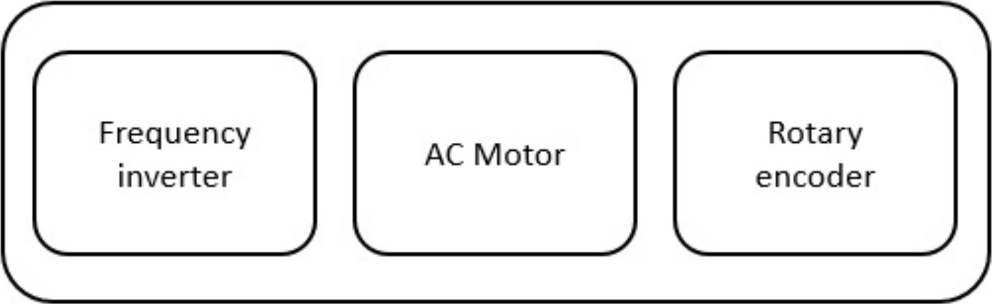
Figura 3
System schematic.
2.2.1. AC motor
The motor used in this project is shown in Figure 4.
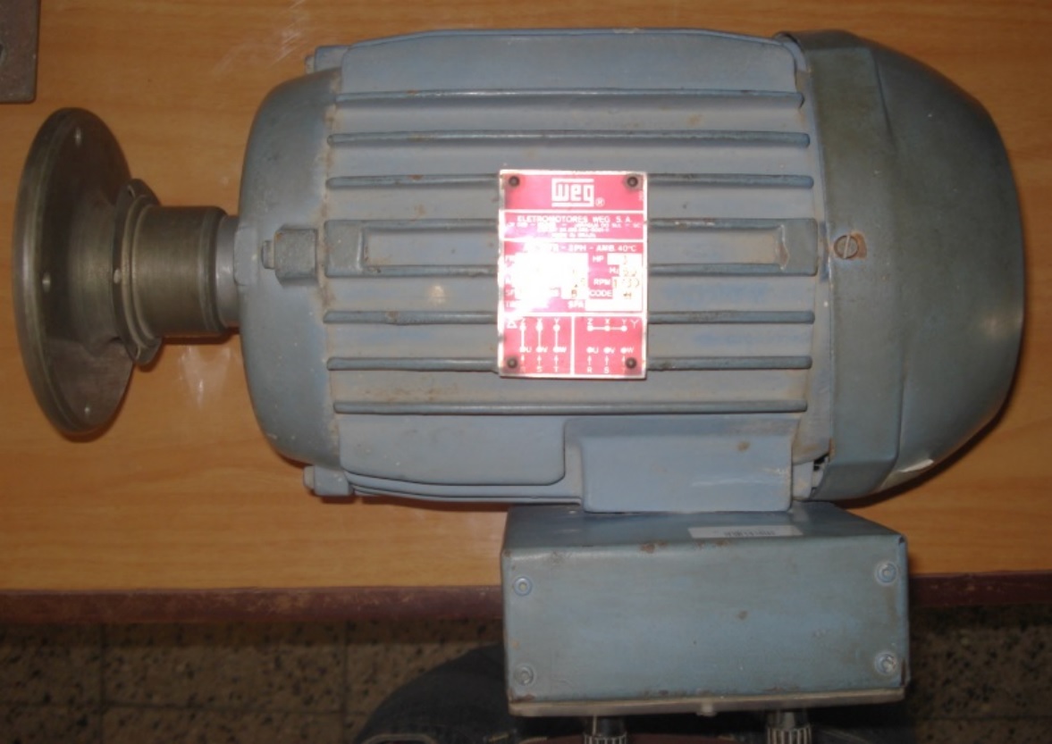
Figura 4
AC motor.
This motor has a squirrel cage rotor and has been fitted with a rotary encoder that allows, once connected to the CLP, to take information of rotor speed in real time. The manufacturer is the Brazilian company WEG and its specifications are shown in Table 1.
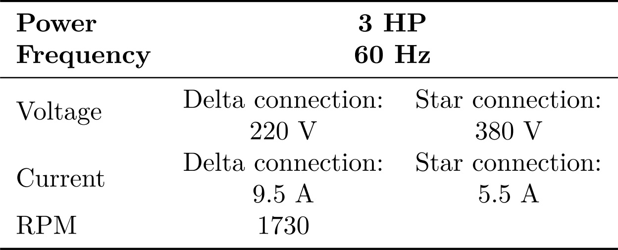
Tabla 1
Motor data plate information
2.2.2. Frequency inverter
The frequency inverter used here is shown in Figure 5, and it is from the manufacturer Delta Electronics INC. model VFD C2000. It is an device with different control modes for AC motors. It has been set to V/F control mode and it is used as the actuator in the system.
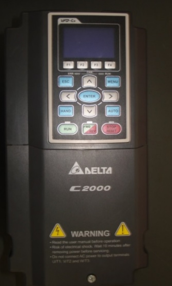
Figura 5
3-phase frequency inverter.
2.2.3. Rotary encoder
To acquire RPM information, rotary encoder HE50B- 8-1024-3-N-24 from manufacturer HANYUNG NUX (shown in Figure. 6) was used.
2.3. Process identification
There are several techniques available to perform system identification, the one presented here is a Linear Parametric Identification technique. This method was selected based on its ease of implementation and due to the possibility of having sufficient data available (input and output data) from the system.
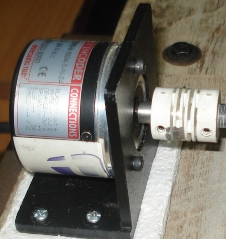
Figura 6
Rotary encoder.
MatLab provides us with the System Identification Tool, which is a specific toolbox designed to help us throughout system identification and it is one of the main software’s we used.To accomplish with the modeling of the system, response of the group drivemotor- encoder is first evaluated and the range of input voltages in which it has a linear response was observed.
Then we proceeded to build a Binary Pseudo Random Sequence (PRBS) signal. Finally using System Identification Tool from MatLab, different approaches of the process were obtained and the one with the highest fit percentage was selected.
2.3.1. System linearity
To determine the range in which the system has linear behavior, different voltage inputs were applied (as step inputs) to the open-loop system and the speed of the motor (RPM), for each voltage input that was registered.
This information is summarized in Table 2 and then a corresponding figure was prepared in order to be able to easily see the range of values where the system has linear behavior.
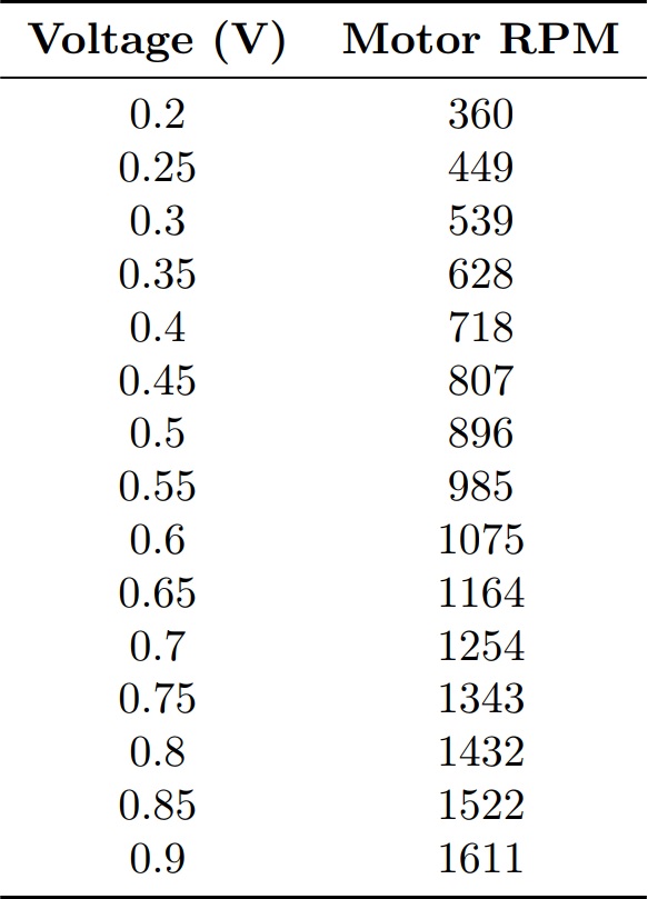
Tabla 2
Voltage input and motor RPM data.
The corresponding graph is shown in Figure 7. Note that the linearity is preserved in all analyzed range; therefore, it was set that identification would be performed between 0.3 V and 0.7 V.
2.3.2. PRBS signal and system response
To prepare the PRBS signal, it is necessary to know the time constant of the process. In order to get this information, a step input was applied to the system, as shown in Figure 8. The green line represents step input and the red line, system response.
In Figure 8, the 63.2% of the set point corresponds to 616 RPM, and it was reached in 3.5 seconds. The maximum period of the PRBS signal must be such as to allow the system response to reach the steady state; therefore, it should be around 3.5 seconds.
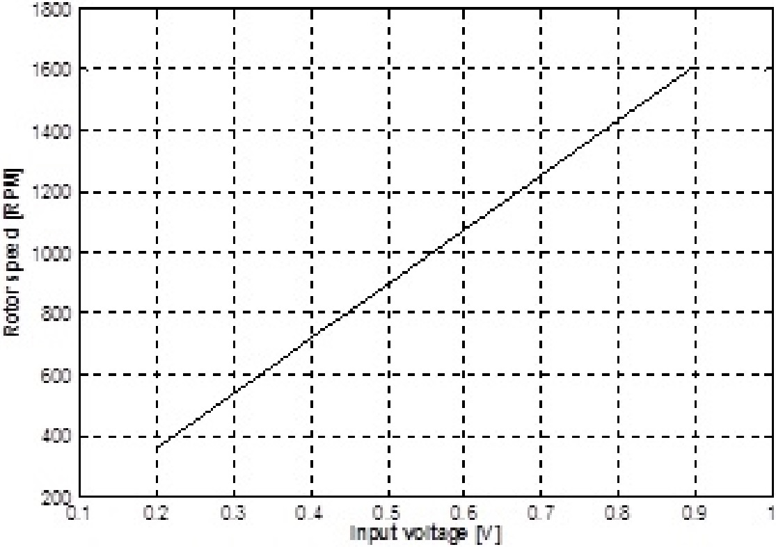
Figura 7
Motor RPM vs. input voltage.
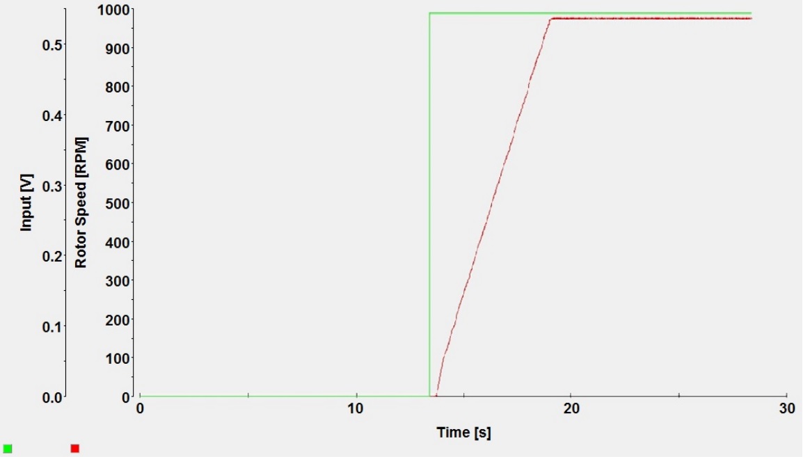
Figura 8
System response to a step input.
Regarding to the minimum signal period, it should be enough to collect system information in small time intervals so we opted for a minimum signal period of1/4 of the time constant, this is 0.875 seconds.
A 300 seconds length PRBS signal was developed in order to have enough information for the identification process.
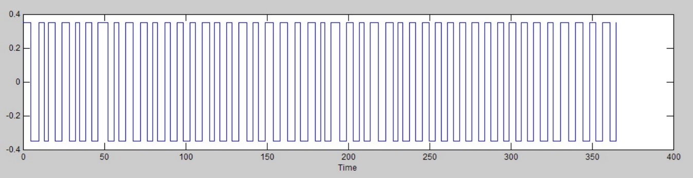
Figura 9
PRBS signal.
2.3.3. Identification
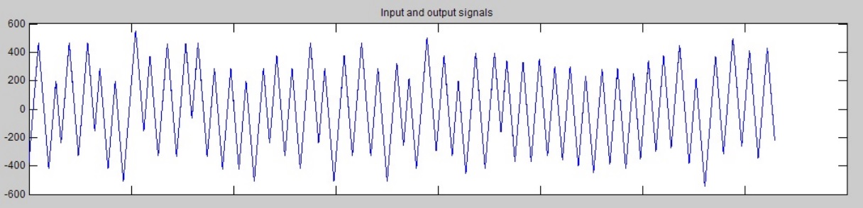
Figura 10
Signal response to PRBS signal.
With the information contained in Figure 9 and Figure 10 we can use System Identification Tool to perform system identification.
In Figure. 11 the five models obtained are shown.
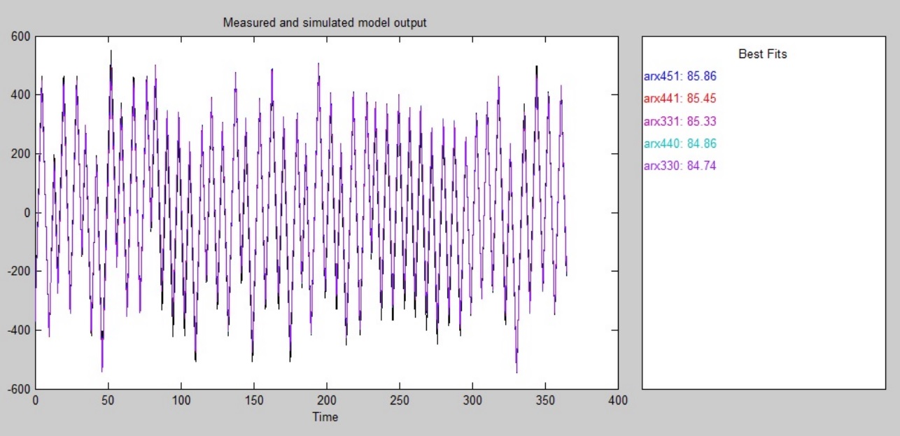
Figura 11
System Identification Tool results.
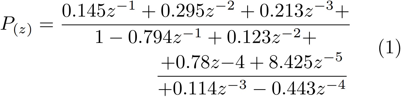
The best approach was obtained using an Auto- Regressive Exogenous (ARX) model (1), reaching 85.86% fit.
2.4. Controller design
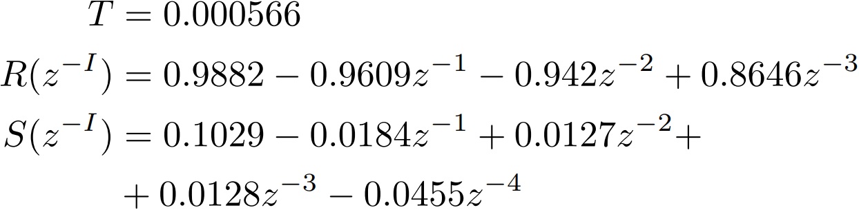
The GPC controller scheme we selected requires the calculation of polynomials R, S and T, necessary for its implementation; we used the equations shown in [8] to develop an iterative program in MatLab and calculate them.
2.4.1. Parameters calculation
After carrying out several tests varying control horizon and lower and upper costing horizons, and by varying the quality/energy ratio in the cost function, the following values were selected:
-
Lower costing horizon: N1 = 1
-
Upper costing horizon: N2 = 500
-
Control horizon: Nu = 500
-
Quality constant: δ
-
= 1
-
Energy constant: λ = 10
With these values, the following parameters were obtained for the controller:
2.5. Load simulation
In order to perform a more exhaustive analysis of the controller, the process is subjected to a load simulation (applied as disturbances and on an intermittent basis) achieved by coupling an electromagnetic brake (shown in Figure 12) to the AC motor shaft.
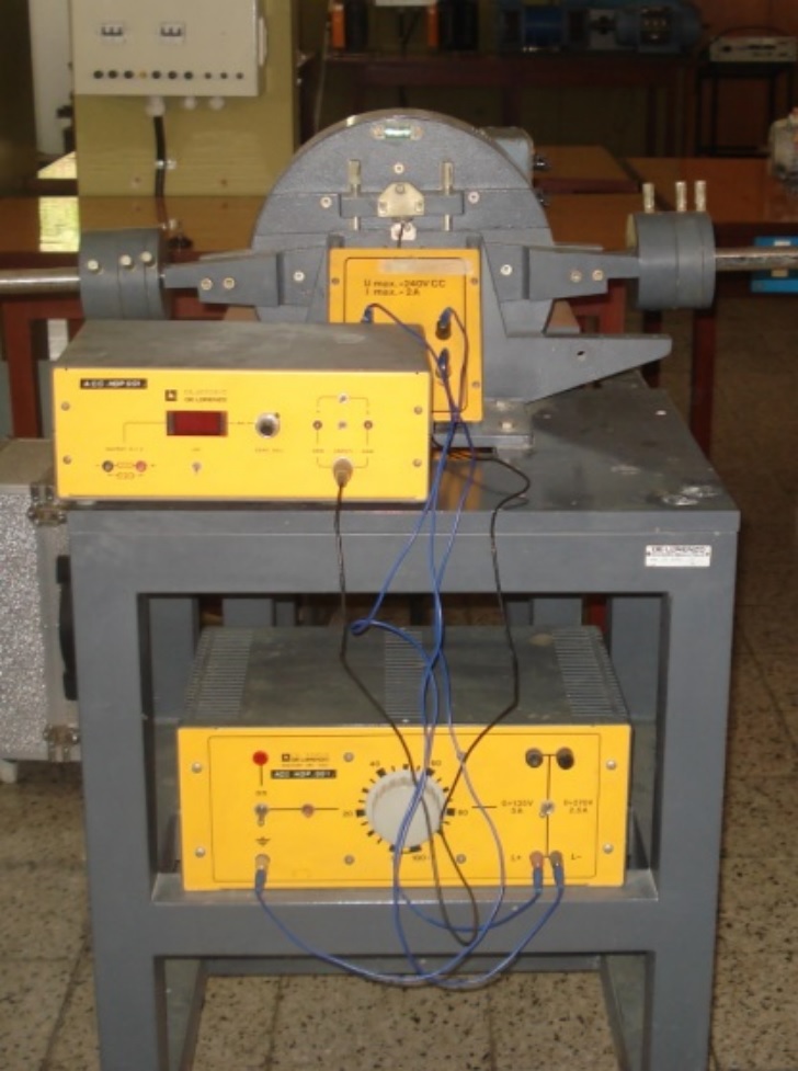
Figura 12
Electromagnetic brake.
3. Results and Discussion
3.1. Controller response
ControlDesk allows us to observe system data in real time. Figure 13 shows that motor speed (red line) corresponds to the values defined by the set point (green line), so we can conclude that the controller design was adequate.
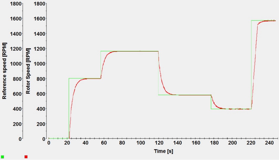
Figura 13
Controller response.
3.2. Controller response to load simulation
To load simulation the electromagnetic brake described above was used. Load was simulated intermittently, in order to observe the regulation of speed against an applied load.
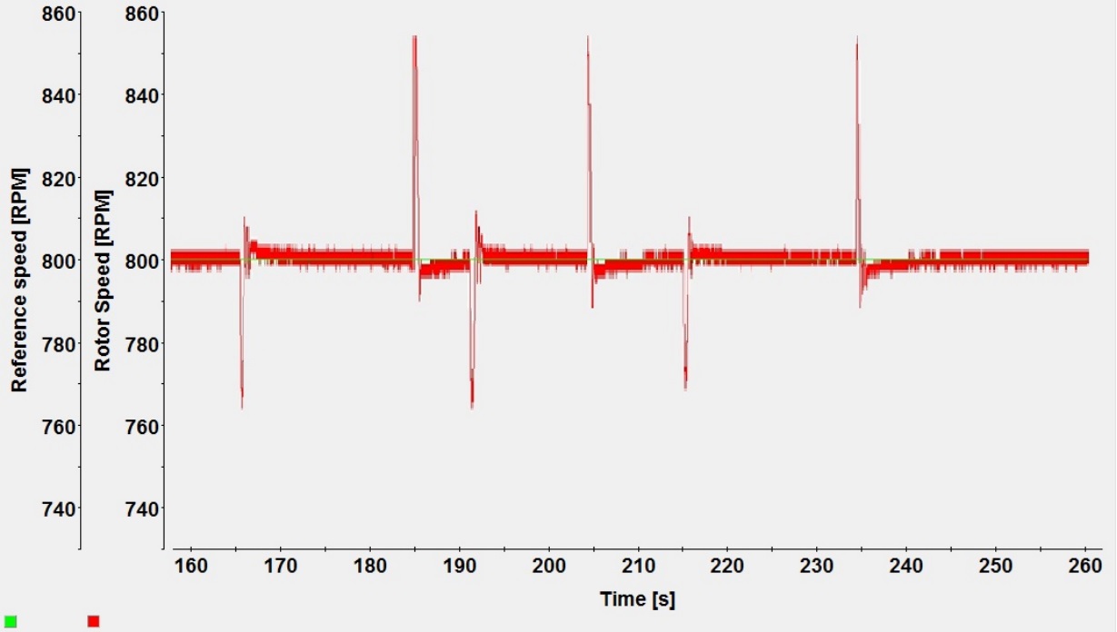
Figura 14
Controller response to load simulation.
Figure 14 shows variations in rotor speed when load is applied. It is easily seen that when load is applied, RPM decreases and the controller proceed to increase velocity to recover the set point value.
On the other hand, when load is removed, RPM tends to increase as torque is high but the controller reduces velocity and the system returns to the set point.
4. Conclusions
We have successfully used dSPACE controller board DS1104, ControlDesk software and MatLab/Simulink to obtain the mathematical model of the system we presented in Figure 3. We were able to find the parameters to perform identification and to make the necessary adjustments in order to achieve the best possible fit percentage.
Likewise, this paper has described the process of development and implementation of a GPC strategy for an induction motor drive system to perform speed control. We have seen the system response to set point variations and its response to load variations, in both cases the controller has shown a good response, so its performance was verified.
Finally, we also demonstrated the capacity of dSPACE platform to accomplish real time control and we can conclude that this platform is a powerful tool for the development of different control methodologies.
References
[1] Z. A. Ghani, M. A. Hannan, and A. Mohamed, “Simulation model of three-phase inverter using dSPACE platform for PV application,” International Review on Modelling and Simulation (I.RE.MO.S.), vol. 5, pp. 137–145, 2012.
[2] P. M. Menghal and A. J. Laxmi, “Real time control of electrical machine and drives: A review,” International Journal of Advances in Engineering & Technology, vol. 1, pp. 112–126, 2011.
[3] J. Versele, O. Deblecker, and J. Lobry, Implementation of Induction Motor Drive Control Schemes in MATLAB/Simulink/dSPACE Envionment for Educational Purpose, K. Perutka, Ed. InTech, 2011.
[4] M. Jemli, H. B. Azza, and M. Gossa, “Real-time implementation of irfoc for single-phase induction motor drive using dspace ds 1104 control board,” Simulation Modelling Practice and Theory, vol. 17, 2009.
[5] A. Soria, R. Garrido, I. Vásquez, and R. Vásquez, “Architecture for rapid prototyping of visual controllers. robot auton syst,” Robotics and Autonomous Systems, vol. 54, pp. 486–495, June 2006. [Online]. Available: http://www.sciencedirect.com/ science/article/pii/S0921889006000121.
[6] dSPACE Catalog 2014, dSPACE GmbH., Paderborn, Germany, 2014.
[7] ControlDesk Experiment Guide, dSPACE GmbH, Paderborn, Germany, 2008.
[8] D. W. Clarke, C. Mohtadi, and P. S. Tuffs, “Generalized predictive control - Part I. The basic algorithm,” Automatica, vol. 23, pp. 137–148, 1987.