Artículos
Risk assessment and corrosion level due to inductions on pipelines close to AC power lines_
Evaluación del riesgo y del nivel de corrosión debido a inducciones en tuberías subterráneas cercanas a redes eléctricas AC

Risk assessment and corrosion level due to inductions on pipelines close to AC power lines_
Revista UIS ingenierías, vol. 22, no. 4, pp. 61-70, 2023
Universidad Industrial de Santander
Received: 10 June 2023
Accepted: 08 September 2023
Published: 03 October 2023
Abstract: A better use of space is achieved when different networks and systems, such as AC transmission lines, transportation systems, and pipelines share the same right-of-way. However, the electromagnetic coupling between the systems may cause the appearance of dangerous conditions for people due to exposure to high touch voltages, as well as for pipelines, caused by the activation of the AC corrosion phenomenon. These dangerous conditions require that during design the possible risks are assessed, and the corresponding mitigation actions are determined. This paper presents a simplified methodology for risk assessment using a practical approach and analytical expressions that can be easily implemented from information known while designing. Likewise, results are included for a case study that allow validating the proposed methodology and demonstrating the importance of this type of analysis.
Keywords: Risk assessment, induction in pipelines, personnel safety, corrosion hazard.
Resumen: Un mejor aprovechamiento del espacio se logra cuando diferentes redes y sistemas, tales como líneas de transmisión AC, sistemas de transporte y tuberías comparten una misma servidumbre de paso. Sin embargo, el acoplamiento electromagnético entre los sistemas puede causar la aparición de condiciones peligrosas para las personas, debido a la exposición a elevadas tensiones de toque, así como para las tuberías, a causa de la activación del fenómeno de corrosión AC. Dichas condiciones peligrosas requieren que durante el diseño se evalúen los posibles riesgos y se determinen las correspondientes acciones de mitigación. En este artículo se presenta una metodología simplificada para el análisis de riesgo usando un enfoque práctico y expresiones analíticas que puede ser implementada de manera sencilla a partir de información conocida durante el diseño. Así mismo, se incluyen resultados para un caso de estudio que permiten validar la metodología propuesta y demostrar la importancia de este tipo de análisis.
Palabras clave: Análisis de riesgo, inducciones en tuberías, seguridad de personas, riesgo de corrosión.
1. Introduction
A problem in electrical systems is the space in which the transmission lines are installed, this is due to environmental restrictions, as well as the location of other types of facilities such as railway tracks and gas or oil pipelines. The Pipeline installations close to AC transmission and distribution lines suffer electromagnetic interference because the electromagnetic field generated by the AC lines produces an induced voltage on the pipeline even if it is underground [1].
The induced voltages on underground pipelines due to magnetic coupling with AC transmission and distribution lines produce hazards to personnel as a consequence of the effects of step and touch voltages in the human body [2], [3]. In addition, these induced voltages can produce degradation of the pipeline insulating coating, and glow and arc discharges can appear on the coating surface [4]. Furthermore, currents through holidays in the pipeline coating involve risk of AC corrosion [5].
Pipelines and AC transmission and distribution lines corridors are frequently placed parallelly, and very close (tens of meters) from each other, to take advantage of the right-of-way of the transmission lines to reduce installations costs. From the point of view of the designer, critical points along the pipelines corridors where the induced voltages exceed threshold values to activate degradation processes, corrosion, risks for step and touch voltages on personnel, should be previously determined for the installation, and protective or corrective strategies must be adopted.
There are different guidelines and directives to calculate the induced voltages on metallic pipelines by AC power systems [4], [6], [7]. The majority are based on inductive coupling and calculations are made using analytical expressions.
In this paper, a simplified analytical methodology to calculate the critical induced voltages on pipelines by parallel AC power lines, and to estimate the hazards to personnel near pipelines and the corrosion level in the pipe is presented and applied to a case study. The results are discussed, and future improvements are also presented.
2. The simplified analytical method
Pipelines and AC transmission and distribution lines are electromagnetically coupled via electrostatic coupling, inductive coupling, and conductive coupling [4]. Due to electrostatic coupling, the electric field related to the AC transmission and distribution lines induce on pipelines currents and voltages which are of interest if pipelines are above ground and insulated from earth. On the other hand, the conductive coupling is related to circulation of electric currents in the soil and buried structures during fault conditions; the injection of fault currents cause ground potential rise of earthed structures and a difference of potential across the pipeline insulating coating. Finally, inductive coupling is caused by the magnetic field created by the currents in the AC lines which induces voltages and currents on pipelines [8].
In this study, we focused on the calculation of effects of inductive coupling between AC lines and underground pipelines under normal conditions. The induced voltages on the pipelines can cause current circulation along the pipeline corridor and potential differences between pipelines and the surrounding soil across the pipeline insulating coating. Additionally, the difference of potential between pipeline and connected accessories, such as valves, fences, etc., involves electric shock hazard to people.
The inductive coupling mechanism is related to the magnetic field produced by the AC transmission and distribution lines, and, as expected, depends on the power transmission line currents and operating conditions, the distance between the power lines and the pipeline, the length of exposure and the characteristics of AC power line.
The simplified analytical methodology can be summarized as follows:
-
The longitudinal component of the electric field along the pipeline corridor, known as the Electromotive Force (EMF), should be calculated. Various distances between the transmission line and the pipeline must be considered to determine the critical distance, where the EMF is maximum. If the distance is known, this is not necessary, and it is assumed that this is the critical distance.
-
The voltages to earth and currents are calculated as resultant of the applied EMF for the critical condition.
-
Voltage distribution profiles along the pipeline corridor are superimposed with the hazard level magnitude for personnel safety, and critical sections are determined.
-
The maximum current density through holidays is calculated and the risk of AC corrosion is estimated.
2.1. Analytical method for calculating the EMF
Induced EMF can be calculated using Electric Circuit Methods (ECM) or Finite Element Methods (FEM) [9], [10], [11]. Using ECM the induced EMF per unit of length along the pipe, E_p (V/km), can be calculated using Equation (1) [12], [13].
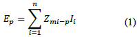
where Zmi-p (Ω/km) is the mutual impedance between the pipe and the ith active conductor in the power line, and Ii (A) is the current in the ith conductor, see Figure 1.
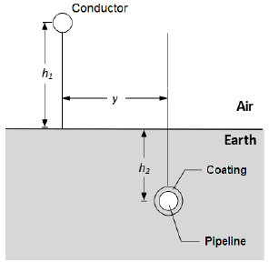
Figure 1
Geometry considered for the EMF calculation.
Source: elaborated by the authors.
The mutual impedance between overhead current carrying conductors and underground insulated pipelines, considering the soil as a lossy media, can be calculated using the Pollaczek's formula [14] as shown in Equation (2).
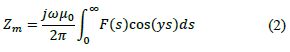
where ω (rad/s) is the angular frequency, μ0 (H/m) is the vacuum permeability, (m) is the horizontal distance between the conductor and the pipe, is the integration variable, and the function F(s) is calculated as shown in Equation (3).
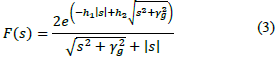
where 𝛾𝑔2=𝑗𝜔𝜇𝑔𝜎𝑔−𝜔2𝜇𝑔𝜀𝑔, 𝜇𝑔, 𝜎𝑔 y 𝜀𝑔 are permeability, conductivity, and permittivity of the soil, respectively, and ℎ1 (m) and ℎ2 (m) are presented in Figure 1.
The solution of Equation (2) requires the implementation of complex numerical methods [15], and some approximated formulas have been proposed by different researchers [14]. Among the approximated formulas, Lucca's formula is accurate enough for most of the study cases in engineering [16]. Lucca's formula is shown in Equation (4).
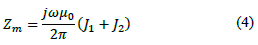
where J1=
 and D =
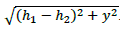
2.2. Induced voltages and current distribution
When the pipeline and surrounding soil are considered as lossy media, the distribution of the voltage to earth along the pipeline, V(x) (V), can be calculated solving the pipeline and surrounding soil equivalent transmissionline model as shown in Figure 2.
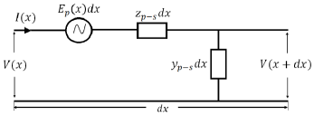
Figure 2
Equivalent transmission line model per unit of length of the electrical circuit of pipeline and the surrounding soil.
Source: elaborated by the authors.
In Figure 2, Ep is the driving induced electromagnetic force (EMF) calculated with Equation (1), zp-s (Ω/m) and yp-s are the series impedance and parallel admittance of the pipeline-soil electric circuit, respectively, calculated as follows in Equations (5) and (6).
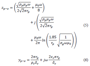
where ρp (Ωm) and μp (H/m) are the resistivity and permeability of the pipeline respectively, rp (m) is the external radius of the pipe, ρc (Ωm) is the resistivity of the coating, δc (m) is the thickness of the coating and εc (F/m) is the permittivity of the pipeline coating.
The differential equations that allow solving the circuit in Figure 2 are shown in Equations (7) and (8).
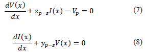
When an ungrounded pipeline extends beyond the parallel route, the analytical solution for equations (7) and (8) are derived in [4], as shown in Equations (9) and
Where L (m) is the length of the parallel route and Yp-s= (1/m) is the coefficient of propagation of the pipeline-soil circuit.
The steps in the methodology described previously related to the electrical risk analysis and corrosion evaluation on pipeline are presented in the case study results section.
3 Case Study
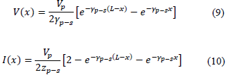
The case study considered in this paper was proposed in [7] and corresponds to a 500 kV AC power transmission line which meets a 0.864 m (34") diameter gas pipeline at the south of California. The average apparent soil resistivity is 400 Ωm, the series impedance of the pipeline-soil circuit per unit of length, zp-s in Figure 2, is 1.031x10⁻⁴+ j5.544x10-4 Ω/m, and the parallel admittance of the pipeline-soil electric circuit per unit of length, yp-s in Figure 2, is 3.980x10⁻⁵+ j1.694x10-7 1/Ωm. The transmission line is horizontally configured with equally spaced conductors, 9.753 m, and the mean height of the phase conductors is h1= 18.287 m. The pipeline is ungrounded and buried at h2 = 0.914 m, see Figure 3.
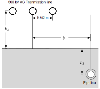
Figure 3
Geometry of the case study. Source: elaborated by the authors.
The current in the phase conductors, from the closest to the farthest conductor to the pipeline, are700 ∠-120° A, 700∠ - 120° A and 700∠0° A, respectively. The distance (m) between the pipeline and the center conductor of the transmission line varies for the purpose of analysis.
3.1. Results
A Scilab© code to solve Equations (1) - (10) was developed, including a graphical user interface. The case study corresponding to Figure 3 was simulated under the conditions described in the previous section. The mutual impedances between the transmission line conductors and the pipeline were calculated using Lucca's formula for different distances between the pipeline and the transmission line. The simulation results are summarized in Table 1.
Source: elaborated by the authors.
Additionally, in the fourth column of Table 1, were included measured values reported in [7] for this case study. The difference between calculated and measured values is presented in the fifth column of Table 1. In the range of distances between 6 and 183 m (20 - 600 ft), the approximated method proposed by Luca allows predicting voltages with a reasonable error, ~ 20 %. The magnitude and phase of the induced EMF as a function of the distance y are presented in Figure 4.
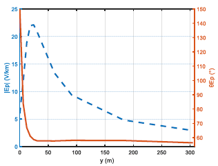
Figure 4
Behavior of the induced EMF magnitude and phase as a function of the distance y.
Source: elaborated by the authors.
In Figure 4, the EMF magnitude reaches a maximum when the distance between the center phase and the pipeline is about twice the distance of separation among the phase conductors. On the other hand, from y =12 m the phase of the EMF remains almost constant at an average value 59.340°.
From Figure 4, it is evident that the voltage distribution along the pipeline will also be dependent on the distance y. Considering for our case study that the length of the parallel route is 10 km and that the pipeline extends beyond the parallel route 5 km in each direction, Figure 5 exhibits the simulation results of voltage and current distributions along the pipeline for distances y of 6.096 m (20 ft), 24.383 m (80 ft) and 91.436 m (300 ft).
From Figures 5 a), c) and e), it is conspicuous that the maximum values of the induced voltage appear at the beginning and end point of the parallel route, while the minimum values are obtained at the middle of the parallel route. On the other hand, from Figures 5 b), d) and f), the maximum value of the induced current appears in the middle of the parallel route. The maximum values obtained for the three different separations considered are summarized in Table 2.
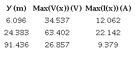
Source: elaborated by the authors.
As expected, the greatest maximum values of induced voltage and current appear for distance y = 24.383 m, where the EMF is the maximum, see Table 1 and Figure 4, this justifies step one in the simplified methodology.
3.1.1. Electrical risk assessment
Once the voltages and currents are calculated, it is necessary to estimate the potential electrical risk to people and the corrosion hazard. Regarding the estimation of the risk to people, international standards as the NACE [2] state a tolerable voltage threshold (hazardous level) of 15 V for personnel safety. It is based on the consideration that the human resistance to electrical AC current at power frequency is about 1500 Ω and currents below 10 mA do not usually cause dangerous pathophysiological effects. On the other hand, there are local standards and normative, that state more restrictive conditions. For example, the RETIE [17] in Colombia, states 1000 Ω as the value of the human body resistance for step and touch voltages calculations.
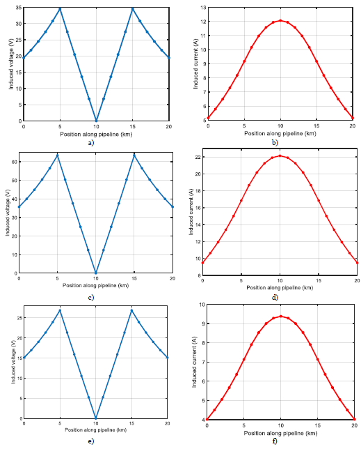
Figure 5
Induced voltage and current distribution along the pipeline a) and b) for y = 6.096 m; c) and d) for y= 24.383 m, and e) and f) for y = 91.436 m.
Source: elaborated by the authors.
Figure 6 shows the time versus current zones of the pathophysiological effects of alternating currents from 15 Hz to 100 Hz, taken from [3], [17].
From Figure 6, it is noticeable that not only the magnitude of the current must be considered, but also the time.
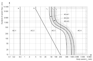
Figure 6
Time/current zones of the effects of alternating currents from 15 Hz to 100 Hz.
Source: IEC [3].
Since the pipelines do not have automatic interrupters of where dh (m) is the holiday diameter. the current, it must be guaranteed that the operating conditions are always limited to zone AC-2, i.e., at most Table 3. Color chart for corrosion risk analysis 10 mA for any exposure time. So, in Colombia, hazardous level must be taken as 10 V.
Superimposing this threshold value on Figures 5 a), c) and e), mitigation actions are required because along most of the length of the pipeline the hazardous level is exceeded. Even points beyond the parallel route exceed it.
3.1.2. Corrosion hazard analysis
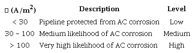
On the other hand, concerning the risk of AC corrosion, the standard BS EN 15280:2013 [18] recommends that the induced voltage should not exceed 10 V where ps≥ 25 fim or 4 V where ps< 25 Ωm. Additionally, as the corrosion rate depends on the current density at holidays in the pipeline coating, J (A/m2), the standard UNE-CEN/TS 15280 [19] states that if J < 30 A/m2 then the pipeline can be considered as protected from AC corrosion; if 30 < J ≤ 100 A/m2, there is medium likelihood of AC corrosion, and if / > 100 A/m2, there is very high likelihood of AC corrosion. Based on this, a color chart can be proposed as shown in Table 3.
Source: elaborated by the authors.
If the risk of corrosion is medium or high, mitigation strategies are required. The current density, /(x) (A/m2), at a holiday location can be calculated using the following expression [20] :
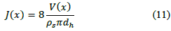
where 𝑑ℎ (m) is the holiday diameter.
In the simplified methodology, it is only necessary to calculate the current density at the points where the maximum values of induced voltages appear. The risk of corrosion is evaluated, and if it is Low, it is not necessary to calculate in any other place along the pipeline corridor. However, if the risk is medium or high, it is necessary to calculate the current density as a function of the position along the pipeline corridor using Equations (9) and (11).
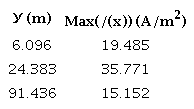
The current densities corresponding to the maximum values in Table 2 were calculated using Equation (11) and considering a holiday of 1 cm2, the results are summarized in Table 4.
Source: elaborated by the authors.
For the case study considered here, a medium likelihood of AC Corrosion according to the standard UNE-CEN/TS 15280 was obtained when the separation between the pipeline and the transmission line was 24.383 m.
The simplified methodology is summarized in the flowchart in Figure 7.
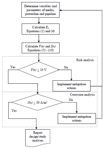
Figure 7
Proposed simplified methodology flowchart.
Source: elaborated by the authors.
Ultimately, in addition to the previous analysis the designer must consider fault conditions depending on the short circuit capacity for evaluating the likelihood of an electric discharge between pipeline and grounded buried structures able to cause pitting and perforation of pipes.
4. Conclusions
In this paper, a simplified methodology for the risks assessment to the safety of people and estimation of corrosion level in pipelines close to AC transmission lines was presented. The methodology is based on a practical approach and well-known analytical expressions.
When comparing the results of the case study with experimental measurements, it was found that the analytical expressions to determine the EMF are sufficiently precise for engineering analysis with an error that is smaller in the range 24.38 m ≤ y ≤ 91.44 m. Additionally, it was found that for distances (y) of up to 9 times the separation between conductors in the AC transmission line, the induced voltages in pipelines can be dangerous for people and mitigation actions are required, as was to be expected since other researchers have estimated the maximum possible interference distance as 200 √𝜌𝑠 m [4].
Likewise, it was shown that along non-parallel sections of pipelines, even at points quite far from the transmission line (5 km), it is still possible to have dangerous voltages for people, so the distribution of voltages must consider the entire route of the pipelines, regardless of its distance or geometry of its route with respect to the transmission line.
Risk analysis is a primary study during the design stage and must be implemented using the most accurate and reliable methods. Future studies will include the analysis under fault conditions and lightning.
References
[1] R. J. Lings, EPRI AC transmission line reference book: 200 kV and above, thirdedition, 3rd ed. Palo Alto, Calif.: Electric Power Research Institute, 2005.
[2] Nace International, NACE SP0177-2014. Mitigation of Alternating Current and Lightning Effects on Metallic Structures and Corrosion Control Systems. Houston, TX, USA, 2014.
[3] International Electrotechnical Commission-IEC, "IEC 60479-1:2018 Effects of current on human beings and livestock General aspects". IEC, Geneva, Switzerland, 2018. [Online]. Available: https://webstore.iec.ch/publication/62980
[4] CIGRE WG 36.02, Guide on the influence of high voltage AC power systems on metallic pipelines. Paris, Fr, 1995. [Online]. Available: https://e-cigre.org/publication/095-guide-on-the-influence-of-high-voltage-ac-power-systems-on-metallic-pipelines
[5] CEOCOR, A.C. Corrosion On Cathodically Protected Pipelines-Guidelines for risk assessment and mitigation measures. 2001. [Online]. Available: https://ceocor.lu/download/AC-Corrosion-Booklet-on-cathodically-protected-pipelines-ed-2001.pdf
[6] ITU, Directives Concerning the Protection of Telecommunication Lines Against Harmful Effects from Electric Power and Electrified Railway Lines. VolumeVI, 1989Edition:Danger and Disturbance, Handbooks on Standardization. Geneva, 2006. [Online]. Available: http://handle.itu.int/11.1002/pub/800dd616-en.
[7] EPRI EL-904, Mutual Design Considerations for Overhead AC Transmission Lines and Gas Transmission Pipelines, Volume 1: Engineering Analysis. Palo Alto, Cal, USA, 1978. Accedido: 15 de junio de 2023. [Online]. Available: Available: https://www.epri.com/research/products/EL-904-V1
[8] L. Bortels, J. Deconinck, C. Munteanu, V. Topa, "A general applicable model for AC predictive and mitigation techniques for pipeline networks influenced by HV power lines", IEEE Trans. Power Deliv., vol. 21, n.o 1, pp. 210-217, ene. 2006, doi: https://doi.org/10.1109/TPWRD.2005.848754
[9] E. Lunca, S. Vornicu, A. Salceanu, O. Bejenaru, "2D Finite Element Model for computing the electric field strength-rms generated by overhead power lines", J. Phys. Conf. Ser., vol. 1065, n.o 5, p. 052024, ago. 2018, doi: https://doi.org/10.1088/1742-6596/1065/5/052024
[10] A. Popoli, L. Sandrolini, A. Cristofolini, "Inductive coupling on metallic pipelines: Effects of a nonuniform soil resistivity along a pipeline-power line corridor", Electr. Power Syst. Res., vol. 189, p. 106621, dic. 2020, doi: https://doi.org/10.1016/j.epsr.2020.106621
[11] H.S. Kim, H. Y. Min, J. G. Chase, C.-H. Kim, "Analysis of Induced Voltage on Pipeline Located Close to Parallel Distribution System", Energies, vol. 14, no 24, 2021, doi: https://doi.org/10.3390/en14248536
[12] G. M. Amer, "Novel technique to calculate the effect of electromagnetic field of H.V.T.L. on the metallic pipelines by using EMTP program", en CIRED2005 - 18thInternational Conference and Exhibition on Electricity Distribution, 2005, pp. 1-5. doi: https://doi.org/10.1049/cp:20051014
[13] G. S. Subcommittee, "Electromagnetic Effects of Overhead Transmission Lines Practical Problems, Safeguards, and Methods of Calculation", IEEE Trans. Power Appar. Syst., vol. PAS-93, n.o 3, pp. 892-904, 1974, doi: https://doi.org/10.1109/TPAS.1974.293989
[14] T. A. Papadopoulos, A. K. Apostolidis, A. I. Chrysochos, G. C. Christoforidis, "Frequency-Dependent Earth Impedance Formulas Between Overhead Conductors and Underground Pipelines", en2019IEEEInternational Conference on Environment and Electrical Engineering and 2019 IEEE Industrial and Commercial Power Systems Europe (EEEIC / I&CPS Europe), 2019, pp. 1-6. doi: https://doi.org/10.1109/EEEIC.2019.8783576
[15] D. A. Tsiamitros, G. C. Christoforidis, G. K. Papagiannis, D. P. Labridis, P. S. Dokopoulos, "Earth conduction effects in systems of overhead and underground conductors in multilayered soils", IEE Proc. - Gener. Transm. Distrib., vol. 153, no. 3, pp. 291299, 2006, doi: https://doi.org/10.1049/ip-gtd:20050195
[16] F. A. Uribe, "Calculating Mutual Ground Impedances Between Overhead and Buried Cables", IEEE Trans. Electromagn. Compat., vol. 50, n.o 1, pp. 198-203, 2008, doi: https://doi.org/10.1109/TEMC.2007.915286
[17] Minenergia, Reglamento Técnico de Instalaciones Eléctricas - RETIE. Bogotá, Col, 2013.
[18] British Standards Institution, BS EN 15280: Evaluation of a.c. corrosion likelihood of buried pipelines applicable to cathodically protected pipelines. London, 2013.
[19] CEN/TS 219, UNE-CEN/TS 15280:2007 IN Evaluación del riesgo de corrosión po...2006. Accedido: 15 de junio de 2023. [Online]. Available: Available: https://www.une.org/encuentra-tu-norma/busca-tu-norma/norma/?Tipo=N&c=N0038400
[20] M. Ouadah, O. Touhami, R. Ibtiouen, "Diagnosis Of The Ac Current Densities Effect On The Cathodic Protection Performance Of The Steel X70 For A Buried Pipeline Due To Electromagnetic Interference Caused By Hvptl", Prog. Electromagn. Res. M, vol. 45, pp. 163171, 2016, doi: https://doi.org/10.2528/PIERM15101103
Notes
Author notes
ajmauricio.rodriguez@udea.edu.cobwalter.villa@udea.edu.co
Conflict of interest declaration