Artículos
Detailed Analysis of Classic Z-source Topology for Protection in DC Power Systems
Análisis detallado de la topología clásica Z-source para la protección de sistemas de alimentación de CC

Detailed Analysis of Classic Z-source Topology for Protection in DC Power Systems
Revista UIS ingenierías, vol. 23, no. 3, pp. 85-92, 2024
Universidad Industrial de Santander
Received: 05 April 2024
Accepted: 16 June 2024
Abstract: This paper presents an in-depth analysis of the classic Z-source topology for DC power system protection, an area previously unexplored in such detail. Using OpenModelica simulations, the study offers valuable insights into the Z-source topology's behavior, protection mechanisms, and energy dissipation processes. It includes detailed diagrams, switching states, and explanations of operating principles, supported by waveforms illustrating energy flow through the Z-source components. The findings demonstrate that the Z-source breaker effectively handles fault conditions by disconnecting the source from the load almost instantaneously, within tens of microseconds. The simulations confirm the theoretical models, showing that the Z-source topology efficiently dissipates fault energy through inductors, capacitors, and resistors, thereby protecting sensitive equipment. This thorough analysis enhances understanding of the Z-source topology in DC power systems and establishes a solid foundation for future research and practical applications.
Keywords: DC power systems, power electronics (PE) devices, Z-source breakers, OpenModelica, DC power systems, DC protection, power switch, energy.
Resumen: Este documento presenta un análisis profundo de la topología Z-source clásica para la protección de sistemas de energía DC, un área previamente no explorada con tal detalle. Utilizando simulaciones en OpenModelica, el estudio ofrece valiosos conocimientos sobre el comportamiento de la topología Z-source, los mecanismos de protección y los procesos de disipación de energía. Incluye diagramas detallados, estados de conmutación y explicaciones de los principios operativos, apoyados por formas de onda que ilustran el flujo de energía a través de los componentes Z-source. Los hallazgos demuestran que el interruptor Z-source maneja eficazmente las condiciones de fallo al desconectar la fuente de la carga casi instantáneamente, en decenas de microsegundos. Las simulaciones confirman los modelos teóricos, mostrando que la topología Z-source disipa eficientemente la energía de fallo a través de inductores, capacitores y resistencias, protegiendo así el equipo sensible. Este análisis exhaustivo mejora la comprensión de la topología Z-source en sistemas de energía DC y establece una base sólida para futuras investigaciones y aplicaciones prácticas.
Palabras clave: Sistemas de potencia de CC, dispositivos de electrónica de potencia (PE), disyuntores de fuente Z, OpenModelica, sistemas de potencia de CC, protección de CC, interruptor de potencia, energía.
1. Introduction
1.1. Background
Microgrids allow for the coordination of distributed energy resources (DERs) and are essential in the energy transition. These small-scale power networks can operate independently or in conjunction with the main grid, providing resilience, reliability, and flexibility [1]. By integrating renewable energy sources like solar and wind, microgrids help reduce carbon emissions and support sustainability efforts. They are particularly valuable in remote areas, where access to the central grid may be limited, and in urban environments, where they enhance energy security and efficiency. As the world moves towards a cleaner energy future, microgrids play a critical role in decentralizing power generation and empowering local communities [2], [3].
Microgrids can operate using either AC (Alternating Current) or DC (Direct Current), each with distinct characteristics and applications. AC microgrids are more common and are typically used in scenarios where the microgrid needs to integrate with the existing main grid, as most conventional electrical infrastructure operates on AC [4]. They are well-suited for residential, commercial, and industrial applications where compatibility with the broader grid is essential. On the other hand, DC microgrids are often used in specific applications like data centers, electric vehicle charging stations, or in renewable energy systems where DC sources, such as solar panels or batteries, are predominant. DC microgrids offer higher efficiency for these applications by eliminating the need for multiple conversions between AC and DC, but they are less compatible with traditional grid infrastructure. The choice between AC and DC microgrids depends on the specific energy needs and the types of loads being served.
1.2. Motivation
The increasing prevalence of DC microgrids and the integration of renewable energy resources have heightened the need for effective protection mechanisms within DC power systems. Traditional circuit breakers face challenges in DC environments due to the lack of naturally occurring current zero crossings, which are essential for interrupting fault currents. Consequently, there is a necessity for advanced protection solutions that can address these challenges and enhance the reliability and safety of DC power systems.
Z-source circuit breakers are primarily used in DC protection systems because they can provide fast and reliable interruption of fault currents. This is critical in DC systems where fault currents can rise rapidly and do not naturally pass through zero as in AC systems. Apart from Z-source circuit breakers, several other protection methods are available for DC systems, including DC fuses, solid-state circuit breakers, current limiting reactors, and fault-tolerant converter designs [5].
While Z-source circuit breakers are frequently mentioned in technical literature, existing works often focus on their applications, benefits, or high-level design without delving deeply into the underlying principles that govern their operation. A detailed understanding of these principles is crucial for engineers and researchers to optimize their use, improve safety, and innovate in the design of DC protection systems. This article seeks to fill this gap by providing an in-depth exploration of the core principles, circuit topologies, and practical considerations that define the functionality and effectiveness of Z-source circuit breakers [6].
1.3. Literature review
Several studies have explored different aspects of DC microgrid protection. A comprehensive review by [7] identifies the types of faults, challenges in protection, and various fault detection schemes in DC microgrids. The study highlights the absence of guidelines and standards, as well as the influence of resistive line impedance on fault clearing times and system stability. Another work by [8] discusses the development of a high-voltage DC circuit breaker utilizing a passive commutation circuit, emphasizing the need for robust and reliable fault interruption methods in high-power applications. Additionally, [9] introduces a figure of merit for power semiconductor devices, indicating that materials with higher mobility and critical electric field for breakdown can significantly reduce power losses in high-frequency circuits. In [10], the authors propose a methodology for coordination of Z-source Circuit Breakers and fuses for Short-circuit protection in DC power networks. In [11], Z-source solid state circuit breakers are reviewed as promising candidates for protecting low and mediumvoltage distribution networks.
Further research has focused on the coordination and optimization of protection devices in DC microgrids. [12] proposes a fuse-saving scheme for DC microgrids with high penetration of renewable energy resources, addressing the issues of bidirectional fault currents and miscoordination between protection devices. [13] evaluates the challenges and recent advancements in DC microgrid protection, emphasizing the need for suitable protection schemes and standards. The challenges of DC fault current characteristics, fault detection methods, and protective devices are extensively reviewed by [14], who also explores future trends in DC microgrid protection. Additionally, [15] discusses the protection considerations in power converter-fed DC systems, highlighting the potential for equipment damage due to capacitive discharge and double ground faults.
The use of Z-source technology for medium voltage networks on ships is proposed in [16]. Through simulations, Z-source performance has been validated for medium voltage at 6.000 V DC, demonstrating instantaneous commutation and fault clearance in tens of microseconds. Furthermore, the paper presents methods for sizing Z-source elements. In [17], a laboratory prototype for low voltage at 400V DC was proposed, yielding positive results. The paper also suggests employing Z-source technology for the protection of power converters supplying motors. In [18], tests were conducted with a low voltage prototype at 280-440V DC and a communication architecture was proposed for DC microgrid implementation.in [19] it is proposed to add resistors to the capacitors to mitigate capacitor inrush currents. Simulations are carried out for medium voltage networks at 6.000V DC, obtaining a reduction of the inrush currents with additional resistors. The concept of the Z-source breaker has emerged as a promising solution for DC protection. The Z-source breaker, as indicated by[20], utilizes a Z-source network comprising inductors and capacitors to enhance protection capabilities. This breaker offers bidirectional blocking, voltage boost capability, enhanced fault tolerance, improved reliability, and efficient energy dissipation during fault conditions.
[16] presents a detailed analysis of the Z-source breaker for medium-voltage DC systems, demonstrating its ability to automatically respond to faults without the need for fault detection and isolate the generation source from fault currents
1.4. Contributions and scope
This paper makes a significant contribution by providing a comprehensive analysis of the classic Z-source topology for DC power system protection. Unlike previous studies, this work delves into unprecedented detail, offering detailed diagrams, switching states, and thorough explanations of the operating principles with illustrative waveforms. The energy dissipation and flow mechanisms are explained and verified through simulations conducted in OpenModelica. This deep analysis not only enhances the understanding of the Z-source topology's protection mechanisms but also provides a solid foundation for future research and practical applications in DC power systems.
1.5. Document organization
This paper is organized as follows: Section 2 describes the proposed methodology. Section 3 presents the explanation of the principle of operation. Section 4 corresponds to the results that include a deep analysis of the principle operation through simulation. Finally, Section 5 concludes and highlights the most relevant aspects of this paper.
2. Methodology
This paper presents a detailed analysis of the classic Z-source topology for DC power system protection, to accomplish this goal a methodology of five steps was developed which is detail bellow.
-
Introduction to Z-Source Topology Analysis: This part of the research begins with a detailed analysis of the principle of operation. The four operating states of the classic Z-source breaker are meticulously described and illustrated.
-
Simulation Using OpenModelica: This phase of the study involves utilizing OpenModelica software to conduct simulations of the Z-source topology. It includes modeling the behavior of Z-source components under different conditions to understand their protection mechanisms and energy dissipation processes.
-
Detailed Diagrams and Explanations: Throughout the document, detailed diagrams are provided to illustrate both the switching states and operating principles of the Z-source topology. Explanations are supported by waveforms that depict energy flow through Z-source components such as inductors, capacitors, and resistors.
-
Fault Handling Evaluation: the research evaluates the Z-source breaker's effectiveness in handling fault conditions, focusing on how it disconnects the source from the load almost instantaneously, within tens of microseconds, during fault occurrences.
-
Validation Through Simulations: This part of the analysis compares the simulation results with theoretical models to validate the findings, demonstrating that the Z-source topology effectively dissipates fault energy through its components, thereby protecting sensitive equipment from damage.
3. Z-source breaker: detailed explanation of principle of operation
The classical Z-source topology offers an interesting research direction for overcurrent fault protection in DC microgrids [21]. It is also referred to as the Cross Z-source topology. Classic Z-source breakers are known for their natural switching process, quick response, simple control system, ability to isolate fault sources, automatic disconnection of faulty loads, and built-in coordination features [22], [23].
Classic Z-source topology is depicted in Figure 1. It is composed of one SCR, two capacitors (C1), (C2) two inductors (L1), (L2) in parallel with diodes (D1), (D2) and resistors (R1),(R2) series array. Assuming that inductors (L1) and (L2), capacitors (C1 ) and (C2), diodes (D1) and (D2) and resistors (R1) and (R2) have the same values (L), (C), (D) and (R) respectively. Z-source is between the voltage source (vs) and load composed of a capacitor (Cl) and a resistor (Rl). Gf is the conductance used to simulate the fault conductance in the load. The aim of the Z-source breaker is safely disconnect the source when a short circuit occurs. Classic Z-source breaker has four operating states that are described as follows: 1) The first state corresponds to steady-state operation, the source vs delivers energy to the load Rl. The currents of the source, SCR, inductors and load are equal in steady state to Il. The current passes through the lowfrequency circuit composed of 0, 1, 2, 3, and 4 which consists of the source, the SCR, inductor L1, load RL and inductor L2; in this state, capacitors C are also charged with the source voltage and they behave as an open circuit (see state 1 Figure 2). 2) Second state is the transient state or fault occurrence state. When a fault occurs in 6, the fault current is supplied by the capacitors C1 and C2 in series and CL. The series capacitors C and CL form a capacitive voltage divider. Current Ic passes through the high-frequency circuit, formed by the capacitors C1 and C2 and SCR following the red line through 7, 6, 9 and 1 in the direction of the source; please see Figure 1. High frequency current of the capacitors increases until is equal to the low frequency current through the inductors IL, then the SCR is reverse biased and commutates off (source is disconnected); please see ISCR in state 2 of Figure 2. 3) Third state, after SCR is turned off, two series LC circuits are connected to the fault and load through 9, 2 and 7, 4; initiating an LC resonance series. Series resonance can be observed when the voltage across the inductor L1 matches the voltage across the capacitor C1 or the voltage across the inductor L2 matches the voltage across the capacitor C2. When the capacitor voltage is reached by the inductor voltage; the voltage at the output becomes zero due to the disconnection of the source. When the resonant voltage of the inductor and capacitor reach half the source voltage, the voltage across the SCR becomes negative. Then the SCR is forward biased. For this reason, one of the functions of the control is to deactivate the gate before the inductor and capacitor voltages at resonance reach half the source voltage or activate the SCR with a single pulse. The resonance ends when voltages in the inductor tend to become negative, please see state 3 of Figure 2. 4) Fourth state begins when the voltage on the capacitor decays to zero after the resonance has ended. Current from the inductors L1 and L2 continues to flow through the diodes and resistors until the current decays to zero, 2, 12, 13 and 4, 10, 11 respectively. The diodes do not allow the inductor current to recharge the capacitor.
![Classic Z-source circuit breaker [16].](../2145-8456-uisi-23-03-85-gf1.png)
Figure 1
Classic Z-source circuit breaker [16].
![Classic Z-source commutation states, adapted from [16].](../2145-8456-uisi-23-03-85-gf2.png)
Figure 2
Classic Z-source commutation states, adapted from [16].
4. Results
Figure 3 shows the implementation of the Classic Zsource topology in OpenModelica.
Fault current (if) , SCR current (ISCR), SCR voltage (VSCR) and load voltage (vL) of classic Z-source topology, are depicted in Figure 4. Figure 4 A) corresponds to the fault current if. Fault occurs in 0.2 s. Please note that if rises to a maximum value and then decreases. When the fault current is increasing, fault clearing events occur in the circuit. When the fault current is decreasing, resonance events occur followed by energy dissipation events in the circuit. Figure 4 B) corresponds to the SCR current ISCR. Before fault occurrence, ISCR has a value of 1.000 A which corresponds to the normal operation of the circuit. After fault occurrence ISCR rapidly decreases to zero for clearing the fault. The commutation process is almost instantaneous and occurs when the fault current increases. Voltage in SCR VSCR and load voltage (v0) are depicted in Figure 4 C. A zero crossing of VSCR is observed which is very important for SCR protection. When vscr crosses zero, the arc generated during switching is mitigated, similar to what happens in AC circuits (please see brown line).
In addition, the load voltage v0 behavior is observed. Once the fault is cleared, the load voltage decays to zero, (please see blue line).
Capacitors current (ic), inductors current (iL), capacitors voltages (vC ), inductors voltage (vL), load current (iRL) and source current (is) of classic Z-source topology are depicted in Figure 5. Figure 5 A) corresponds to the moment when the transient current of the capacitor (red line) reaches the steady state, current of the inductor (green line) is observed. In this instant time, the commutation occurs. After disconnection, capacitor current and inductor current are equal because they are connected in series. In Figure 5 B), the series resonance lapse is observed. When the inductor voltage (blue line) is equal to the capacitor voltage (brown line), it corresponds to the series resonance time. Once the resonance is finished, the voltage across the capacitor decays to zero, inductor voltage decays to zero and intend to become negative. Once the resonance is finished, the current across the capacitor decays to zero and the current in the inductor continues to circulate in the circuit snubber. In Figure 5 C), the behavior of the current in the source and the current in the load are depicted. Once fault clearance has occurred, the current in the source (violet line) immediately decays to zero and the current in the load (black line) that also dacays to zero. In effect, classic Z-source topology simultaneously protects the source and the load.
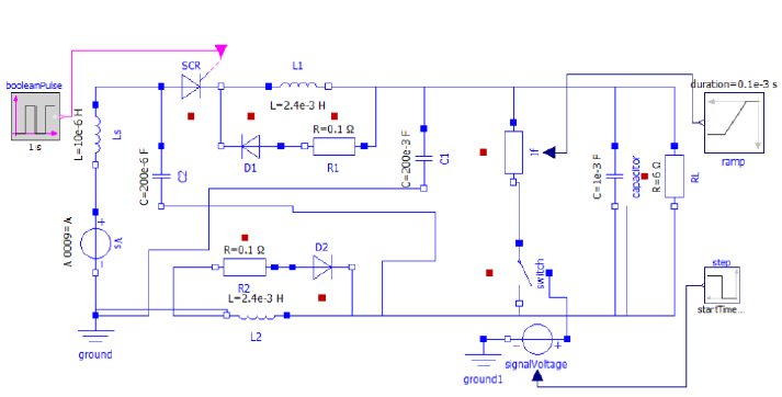
Figure 3
OpenModelica simulation of classic Z-source topology.
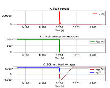
Figure 4
Classic Z-source behavior if , iSCR , vscr,v0
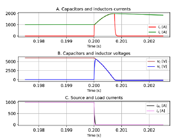
Figure 5
Classic Z-source behavior ic , iL , vc , vL , iRL , is
Fault (if ) and capacitors (ic) currents of classic Zsource topology are depicted in Figure 6. It is observed that the current through the capacitor is only 6% of the fault current. This occurs because the capacitor current does not depend directly on the fault current, but rather on the variation of the voltage in the inductor (please see Figure 6).
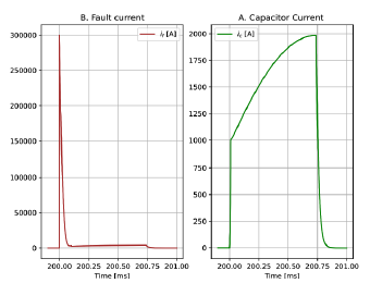
Figure 6
Classic Z-source behavior if , ic
5. Conclusions
This research paper provided a comprehensive and detailed analysis of the classic Z-source topology for protection in DC power systems, significantly advancing the understanding of this technology. The simulations conducted in OpenModelica offer unprecedented insights into the behavior and protection mechanisms of the Z-source topology, demonstrating its efficacy and reliability. The paper presents an in-depth explanation of the operating principles of the Z-source breaker, including the different states of operation and the associated waveforms. This detailed analysis helps in understanding how energy dissipation and flow occur through the Z-source components during fault conditions. The insights gained from this analysis provide a solid foundation for future research and practical applications. The detailed diagrams, switching states, and waveforms presented in this paper can serve as valuable references for engineers and researchers working on DC power system protection.
The use of OpenModelica for simulating the Z-source topology has validated the theoretical explanations provided. The results confirm that the Z-source breaker operates as expected, with the SCR current, fault current, and load voltage behaving in accordance with the theoretical predictions. The study highlights the energy dissipation mechanisms within the Z-source topology. The resonance between inductors and capacitors, followed by the energy dissipation through resistors, ensures that the fault energy is safely managed, preventing damage to the system components. The classic Z-source topology effectively disconnects the source from the load during fault conditions. The simulations show that the Z-source breaker can clear faults almost instantaneously, in tens of microseconds, which is crucial for protecting sensitive equipment in DC power systems.
References
J. E. Santos-Ramos, S. D. Saldarriaga-Zuluaga, J. M. López-Lezama, N. Muñoz-Galeano, W. M. Villa-Acevedo, "Microgrid protection coordination considering clustering and metaheuristic optimization," Energies, vol. 17, no. 1, 2024, doi: https://doi.org/10.3390/en17010210
Y. Zahraoui, T. Korõtko, A. Rosin, T. E. K. Zidane, H. Agabus, S. Mekhilef, "A competitive framework for the participation of multimicrogrids in the community energy trading market: A case study," IEEE Access, vol. 12, pp. 68 232-68 248, 2024, doi: https://doi.org/10.1109/ACCESS.2024.3399168
W. Guedes, C. Oliveira, T. A. Soares, B. H. Dias, M. Matos, "Collective asset sharing mechanisms for pv and bess in renewable energy communities," IEEE Transactions on Smart Grid, vol. 15, no. 1, pp. 607-616, 2024, doi: https://doi.org/10.1109/TSG.2023.3288533
J. Lu, B. Zhang, X. Hou, J. M. Guerrero, "A distributed control strategy for unbalanced voltage compensation in islanded ac microgrids without continuous communication," IEEE Transactions on Industrial Electronics, vol. 70, no. 3, pp. 2628-2638, 2023, doi: https://doi.org/10.1109/TIE.2022.3169841
M. W. Altaf, M. T. Arif, S. N. Islam, M. E. Haque, "Microgrid protection challenges and mitigation approaches-a comprehensive review," IEEE Access, vol. 10, pp. 38 895- 38 922, 2022, doi: https://doi.org/10.1109/ACCESS.2022.3165011
S. K. Prince, S. Affijulla, G. Panda, "Protection of dc microgrids based on complex power during faults in on/off-grid scenarios," IEEE Transactions on Industry Applications, vol. 59, no. 1, pp. 244-254, 2023, doi: https://doi.org/10.1109/TIA.2022.3206171
S. Augustine, J. E. Quiroz, M. J. Reno, S. Brahma, "Dc microgrid protection: Review and challenges," U.S. Department of Energy Office of Scientific and Technical Information, United States, Tech. Rep., 8 2018.
B. Bachmann, G. Mauthe, E. Ruoss, H. Lips, J. Porter, J. Vithayathil, "Development of a 500kv airblast hvdc circuit breaker," IEEE Transactions on Power Apparatus and Systems, vol. PAS-104, no. 9, pp. 2460-2466, 1985, doi: https://doi.org/10.1109/TPAS.1985.318991
B. Baliga, "Power semiconductor device figure of merit for high-frequency applications," IEEE Electron Device Letters, vol. 10, no. 10, pp. 455- 457, 1989, doi: https://doi.org/10.1109/55.43098
R. Fu, K. C. Montross, "A new method of coordinating zcbs and fuses for a reliable shortcircuit protection in dc power networks," IEEE Access , vol. 10, pp. 63 270-63 279, 2022, doi: https://doi.org/10.1109/ACCESS.2022.3183234
C. E. Ugalde-Loo, Y. Wang, S. Wang, W. Ming, J. Liang, W. Li, "Review on Z-source solid state circuit breakers for dc distribution networks," CSEE Journal of Power and Energy Systems, vol. 9, no. 1, pp. 15-27, 2023, doi: https://doi.org/10.17775/CSEEJPES.2022.04320
N. Bayati, H. R. Baghaee, A. Hajizadeh, M. Soltani, "A fuse saving scheme for dc microgrids with high penetration of renewable energy resources," IEEE Access , vol. 8, pp. 137 407-137 417, 2020, doi: https://doi.org/10.1109/ACCESS.2020.3012195
N. Bayati, A. Hajizadeh, M. Soltani, "Impact of faults and protection methods on dc microgrids operation," in 2018 IEEE International Conference on Environment and Electrical Engineering and 2018 IEEE Industrial and Commercial Power Systems Europe (EEEIC / I CPS Europe), pp. 1-6, 2018, doi: https://doi.org/10.1109/EEEIC.2018.8494631
S. Beheshtaein, M. Savaghebi, J. C. Vasquez, J. M. Guerrero, "Protection of ac and dc microgrids: Challenges, solutions and future trends," in IECON 2015 - 41st Annual Conference of the IEEE Industrial Electronics Society, pp. 005 253-005 260, 2015, doi: https://doi.org/10.1109/IECON.2015.7392927
R. Cuzner, D. MacFarlin, D. Clinger, M. Rumney, G. Castles, "Circuit breaker protection considerations in power converter-fed dc systems," in 2009 IEEE Electric Ship Technologies Symposium, pp. 360-367, 2009, doi: https://doi.org/10.1109/ESTS.2009.4906537
K. A. Corzine, R. W. Ashton, "Structure and analysis of the z-source mvdc breaker," in2011IEEE Electric Ship Technologies Symposium, pp. 334-338, 2011, doi: https://doi.org/10.1109/ESTS.2011.5770893
K. A. Corzine, R. Ashton, "A new z-source dc circuit breaker," IEEE Transactions on Power Electronics, vol. 27, no. 6, pp. 2796-2804, 2012, doi: https://doi.org/10.1109/TPEL.2011.2178125
A. Maqsood, A. Overstreet, K. A. Corzine, "Modified z-source dc circuit breaker topologies," IEEE Transactions on Power Electronics , vol. 31, no. 10, pp. 7394-7403, 2016, doi: https://doi.org/10.1109/TPEL.2015.2511588
P. Prempraneerach, M. G. Angle, J. L. Kirtley, G. E. Karniadakis, and C. Chryssostomidis, "Optimization of a z-source dc circuit breaker," in2013 IEEE Electric Ship Technologies Symposium (ESTS), pp. 480-486, 2013, doi: https://doi.org/10.1109/ESTS.2013.6523780
T. Li, Y. Li, N. Liu, "A new topological structure of z-source dc circuit breaker," IEEE Transactions on Circuits and Systems II: Express Briefs, vol. 69, no. 7, pp. 3294-3298, 2022, doi: https://doi.org/10.1109/TCSII.2022.3156575
L. Yi, J. Moon, "Bidirectional q-z-source dc circuit breaker," IEEE Transactions on Power Electronics , vol. 37, no. 8, pp. 9524-9538, 2022, doi: https://doi.org/10.1109/TPEL.2022.3153889
V. R. I, S. N. Banavath, S. Thamballa, "Modified z-source dc circuit breaker with enhanced performance during commissioning and reclosing," IEEE Transactions on Power Electronics , vol. 37, no. 1, pp. 910-919, 2022, doi: https://doi.org/10.1109/TPEL.2021.3092773
Z. Zhou, J. Jiang, S. Ye, D. Yang, J. Jiang, "Novel bidirectional o-z-source circuit breaker for dc microgrid protection," IEEE Transactions on Power Electronics , vol. 36, no. 2, pp. 1602- 1613, 2021, doi: https://doi.org/10.1109/TPEL.2020.3006889
How to cite:
Funding acquisition
Autor Contributions
Institutional Review Board Statement
Informed Consent Statement
Author notes
aEmails: bayron.perea@udea.edu.cobnicolas.munoz@udea.edu.cocjmaria.lopez@udea.edu.co
Conflict of interest declaration