Article
Using Smartphones as a Measurement Platform in Geoscience Applications
Utilizando Smartphones como Plataforma de Mensuração para Aplicações na Geociência
 Livia Faria Sampaio liviafariasampaio@gmail.com
Luís Augusto Koenig Veiga kngveiga@gmail.com
Samir de Souza Oliveira Alves samir.alves@eng.uerj.br
Livia Faria Sampaio liviafariasampaio@gmail.com
Luís Augusto Koenig Veiga kngveiga@gmail.com
Samir de Souza Oliveira Alves samir.alves@eng.uerj.br
Using Smartphones as a Measurement Platform in Geoscience Applications
Anuário do Instituto de Geociências, vol. 46, 56179, 2023
Universidade Federal do Rio de Janeiro
Received: 21 December 2022
Accepted: 14 April 2023
Funding
Funding source: CAPES
Contract number: Nº001
Funding statement: CAPES, Process Nº001.
Abstract: Most modern smartphones come with a variety of sensors. Among them are the gyroscope, accelerometer, magnetometer, GNSS (Global Navigation Satellite Systems) receiver, and from 2020, most modern devices are also coupled with a Lidar (Light Detection and Ranging) sensor. These specific sensors allow to acquire data that enables the location and spatial orientation of the smartphone in relation to other objects, and also measure them. For this, it is important to understand how the principle of operation of these sensors occurs, as well as the respective raw data obtained and how to use these data from the sensors to get measurements of the elements of the physical surface of the Earth. This article aims to present a state of the art about the working principle of these sensors and presents the raw data from them. In addition, this article seeks to present an initial test on the quality of the orientation sensor, based on the comparison between the data obtained from this sensor and a total station with high angular precision (1 second). It was noted the occurrence of a systematic error in the observations of the horizontal directions, and an average discrepancy of 5.20° between the observations of the vertical angle. The use of sensors attached to smartphones can support in several activities of geoscience application, such as carrying out a prior survey of a given area of study, aiming to do a pre-analysis of geodetic networks, to carry out measurements of angles and distances for applications in terrain measurements, or even to assist the Geographic Information System (GIS) development.
Keywords: Smartphones, Sensors, Measurements.
Resumo: Os smartphones modernos vêm com uma variedade de sensores. Entre eles estão o giroscópio, acelerômetro, magnetômetro e receptor GNSS (Global Navigation Satellite Systems) e, a partir de 2020, alguns dispositivos mais modernos são equipados com sensores Lidar (Light Detection and Ranging). Esses sensores específicos mencionados possibilitam obter dados que permitem que a localização e orientação espacial do smartphone em relação a outros objetos possam ser medidos e medidos a partir deste dispositivo. Para isso, é importante entender como ocorre o princípio de funcionamento desses sensores, bem como os respectivos dados brutos, obtidos e como utilizar esses dados dos sensores para realizar medições dos elementos da superfície física da terra. Este artigo tem como objetivo apresentar um Estado da arte sobre o princípio de funcionamento desses sensores e apresentar os dados brutos obtidos a partir deles. Além disso, este artigo busca apresentar um teste inicial sobre a qualidade do sensor de orientação, a partir da comparação entre os dados obtidos entre este sensor e uma estação total de alta precisão angular (1 segundo). Observou-se a ocorrência de um erro sistemático nas observações das direções horizontais, e uma discrepância média de 5.20° entre as observações do ângulo vertical. A utilização dos sensores acoplados nos smartphones podem auxiliar em diversas atividades na área de geociências, como por exemplo, para a realização de um levantamento prévio de uma determinada área de estudos, visando a realização de pré-análise de redes geodésicas, ou a realização de mensurações de ângulos e distâncias para aplicações que envolvem medidas de um terreno, ou mesmo para auxiliar no desenvolvimento de Sistema de Informação Geográfica (SIG).
Palavras-chave: Smartphones, Sensores, Medidas.
1 Introduction
Advances in technology have enable the development of tools to automate and control the process of measurements using mobile devices such as tablets and smartphones. The use of these devices does not replace high-precision equipment used in Geodesy. But they have become useful tools in activities that help, for example, the planning and control of field activities.
Daponte et al. (2013) present a state of the art of the measurement applications used in smartphones. These authors present a definition of modern smartphones as equipment that contain different sensor technologies, so that they can be used as measuring instruments. In addition, they also present a review of applications that use smart sensors and the communication interfaces available in these devices.
Within the Geodetic Sciences, some studies have already been developed in the context of the use of smartphones for different applications such as: Geographic Information Systems (GIS); photogrammetry, as applications developed for aerophotogrammetric flight planning monitoring of structures and surveys with GNSS receivers (Conti, Ribeiro & Dias 2015; Hwang et al. 2012; Peres et al. 2015; Sampaio et al. 2022)
For the development of these applications, it is necessary to use raw data from the different sensors embedded in smartphones. This paper seeks to present a state of the art of how the principle of operation of some sensors present in smartphones occurs, in addition to seeking to present what are the raw data that can be obtained through them and the respective quality of this data. The main sensors used for the spatial positioning of the devices will be presented, considering the sensors for positioning and that allow the realization of measurements with them.
2 MEMS-Type Sensors and the Coordinate System of these Sensors
Smartphones have sensors attached to these devices that are based on a technology known as Micro Electro-Mechanical Systems (MEMS). The acronym MEMS in American nomenclature or Micro Systems Technology (MST) in Europe, are integrated circuits consisting of mechanical parts.
The components of MEMS are formed by a silicon substrate. These devices can be of two types, microsensors and micro actuators. Microsensors have the function of collecting information from the surrounding environment through their mechanical, magnetic, thermal, chemical, and optical elements. The function of micro-actuators is to act as needed through mechanisms such as filters, actuators, valves, and motors. All these functions are performed by these microscopic-sized, highly efficient, reliable, economical, and low-cost devices (Stuhler 2022).
MEMS technology is used for the development of sensors, such as the accelerometer, gyroscope, and magnetometer, which have three axes, as shown in Figure 1.
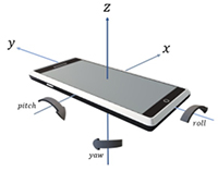
For most sensors, the coordinate system is set relative to the device's screen when the device is held in the default orientation, i.e., when the smartphone is in portrait position. In this case, the “X” axis is horizontal and points to the right, the “Y” axis is vertical and points up, and the Z axis points away from the screen. In this system, the coordinates behind the screen have negative Z values (Android 2022).
The Inertial Measurement Unit (IMU) acronym for inertial measurement unit, is an inertial platform from a system composed of sensors that informs the position of an object to be measured in relation to its rotation axes. The sensors that make up the inertial system are usually the gyroscope, accelerometer and magnetometer that serve to measure orientation, acceleration, and magnetic direction (Figure 2). From the combination of these sensors, it is possible to obtain the device orientation angles. Each sensor can act on three different axes. The three axes of these sensors provide the roll, pitch, and yaw angles (Figure 1) (Kuhlmann, Garaizar & Reips 2021; Stuhler 2022).
The roll angle varies as the device is moved about the “Y” axis. When the device is level, this angle has a value of 0°, and varies from 90° to -90°, when the device is tilted up on the left side, and when the device is tilted up on the right side respectively. The pitch varies as the device is moved about the “X” axis. It has a value of 0° when the device is level and varies between 90° and 180° as the device is tilted so that its top is pointing down. Likewise, as the device is tilted downwards, the angle varies from -90° to -180° as it is rotated (MIT 2020).
The yaw angle corresponds to the magnetic azimuth and varies as the device is moved around the “Z” axis. Measures 0° when the top of the device is pointing to magnetic north; 90° when pointing east; 180° when pointing south; and 270° when pointing west. These measurements assume that the device itself is not moving (MIT 2020).
The most important feature to understand about this coordinate system is that the axes are not switched when the device's screen orientation changes, i.e., the sensor coordinate system never changes as the device is moved. It cannot be assumed that the natural (default) orientation of the device is portrait. The natural orientation of many tablets is the landscape. The sensor coordinate system is always based on the device's natural orientation (Android 2022).
3 Quality of Orientation Sensor
Within the context of using data from smartphone sensors to measure angles, Kuhlmann, Garaizar and Reips (2021) presented a study on the accuracy of this data, especially about sensors that allow the smartphone’s orientation to be obtained. These authors made a comparison between the different smartphone models present on the market, and consequently the different types of sensors embedded in each of these devices.
This study investigated the accuracy of the orientation data on the spatial position of smartphones through a measurement device developed by them. The smartphone's pitch (vertical orientation) and roll (horizontal orientation) angle data were compared to data collected from sensors through applications developed in web browsers and from native applications. The accuracies achieved differed between smartphone models, with average inaccuracies per device of up to 2.1° and 6.6°, respectively for pitch and roll. The results of this research confirm the presence of heterogeneities when collecting orientation data from different smartphone devices. In most cases, measuring via a web browser was identical to measuring via a native app, but this was not true for all smartphone devices.
The authors Oh and Kim (2020) carried out research related to the determination of azimuths from the geomagnetic sensor. These authors point out that it is difficult to use the azimuths obtained from this sensor, because the accuracy cannot be determined even in places where the geomagnetic disturbance can be compensated. In this research the authors propose a new algorithm that employs the accelerometer, gyroscope, and geomagnetic sensor data to determine the accuracy of the initial azimuth orientation. Azimuth angle measurement using geomagnetic sensors is unreliable due to distortion of the Earth's magnetic field.
Data on the accuracy of spatial orientation are performed primarily based on investigation of external influences on accuracy and natural deviations from values (Grewal & Andrews 2010). One of these external factors is the influence of the temperature at which the orientation sensor operates. Temperature change results in inaccuracies in the readings. Because this inaccuracy is predictable and consistent, most orientation sensors are coupled with a temperature sensor. Another source of inaccuracies is acceleration and vibration. This is especially a problem for compact orientation sensors without much damping that are implemented in mobile devices (Weinberg 2011).
3.1 Sensors Embedded in Smartphones
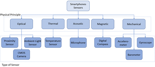
The author Daponte et al. (2013) classifies the sensors according to their physical principle of operation, which can be: optical, thermal, acoustic, magnetic, or mechanical (Figure 3).
While sensor availability varies by device, it may also vary between the operating system versions. That is why it is important to know which operating system and which version is being used to verify whether it is possible to use data from certain sensors.
According to Oliveira et al. (2014), smartphones have an operating system whose main function is to manage all the applications and hardware processes of a device. Android is currently the most used operating system in smartphones available on the market (83.8% of the world market in 2020 - IDC 2020). The author also points that Android is a Linux-based operating system designed for smartphones and tablets but can be found on other devices such as digital cameras, TVs, and even video games. It allows the source code to be modified, but Google requires the modified version to work in all applications available on Google Play (Android Web Store).
Most devices have built-in sensors that generate raw data with high accuracy and are useful for monitoring three-dimensional motion or positioning or for tracking changes in the surrounding environment. The Android platform supports three broad categories of sensors (Android 2022):
• Motion sensors: measure rotational and acceleration forces in three axes. This category includes accelerometers, gravity sensors, gyroscopes, and rotation vector sensors;
• Environmental sensors: measure various environmental parameters such as ambient air temperature and pressure, lighting, and humidity. This category includes barometers, photometers, and thermometers;
• Position sensors: measure the physical position of a device. This category includes orientation sensors and magnetometers.
3.2 Hardware Sensors, Software Sensors and Ways to Obtain Sensors Data
Experiments on mobile devices can be performed using native and web applications. Native apps run on top of the device's operating system and use compiled code (i.e., Java/Kotlin for Android devices, Objective-C/Swift for iOS devices). Web applications run in a web browser (Google Chrome, Apple Safari, Mozilla Firefox) and use web Application Programming Interfaces (APIs) through JavaScript language code. In addition, there are some application development platforms, the so-called “frameworks” (Xamarin, Appcelerator, Adobe PhoneGap) that can port their code to multiple platforms (Kuhlmann, Garaizar & Reips 2021).
These frameworks allow accessing various types of sensors. Some of them are hardware based while others are software based (Table 1). Hardware-based sensors are physical components built into a mobile device or tablet. They derive data by directly measuring specific environmental properties such as acceleration, geomagnetic field strength or angular change. Software-based sensors are not physical devices, although they mimic hardware-based sensors. These derive data from one or more hardware-based sensors and are known as virtual or synthetic sensors. The linear acceleration sensor and the gravity sensor are examples of software-based sensors (Android 2022; Kuhlmann, Garaizar & Reips 2021).
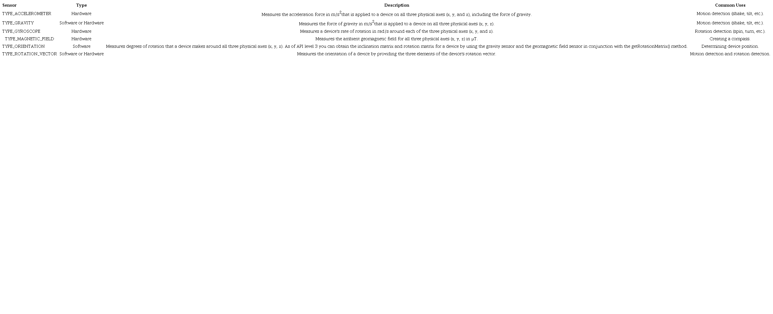
Native apps can collect data from hardware sensors directly, while web apps are unable to do this for security reasons. However, most native mobile apps do not receive values directly from sensors, but data from software sensors (Kuhlmann, Garaizar & Reips 2021; Android 2022). In Table 1, it is possible to verify, for example, the types of sensors compatible with the Android platform and classified as being Hardware sensors, software sensors, and those that can be both hardware and software sensors.
Software sensors provide estimates of actual position, orientation, and motion values by combining readings from various hardware sensors such as accelerometers, gyroscopes, magnetometers, or barometers. The hardware sensors in today's smartphones are like circuit chips in appearance and work electronically. The use of software sensors is considered a good development strategy as it allows the integration of values obtained from different sensors (Kuhlmann, Garaizar & Reips 2021).
4 Gyroscope
The gyroscope is a device that determines orientation through angles. It has applicability in sectors such as aviation, computing, robotics and in mobile devices such as video games, cell phones, among others. There are several types of gyroscopes, including Mechanical scopes, Ring Laser Gyroscopes (RLGs), Fiber-Optic Gyroscopes (FOGs) and silicon MEMS Gyroscopes, the latter used in cell phones and mobile devices because it has minimal cost and is easy to manufacture (Passaro et al. 2017). The MEMS-type gyroscope uses the Coriolis effect to explain the direction and change in this direction. The Coriolis effect can be explained as follows, starting with Figure 4.
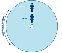
Consider a person standing on a turntable, near the center. Your velocity relative to the ground is shown as the lengths of the blue arrows. If that person were to move to a point near the outer edge of the platform, their speed would increase relative to the ground, as indicated by the longer blue arrow. The rate of increase of its tangential velocity, caused by its radial velocity, corresponds to the Coriolis acceleration (Watson 2016). The Coriolis effect states that in a frame rotating at an angle of velocity ω, a mass m moving with velocity v experiences a force (Equation 1) (Qazizada & Pivarčiová 2016):
F = - 2m(wxV) (1)
A microelectromechanical gyroscope (MEMS) instead of rotating disk to measure angular velocity, it uses a structure like the accelerometer through capacitance variation, but instead of measuring displacement, it measures angular velocity through the force of Coriolis.
A mass moving in a direction with a certain speed and when an external angular rate (rotation process) is applied, a resultant force will appear causing the perpendicular displacement of this mass (Figure 5), this displacement changes the capacitance of the circuit that will be measured, processed, and will correspond to a certain angular rate (Stuhler 2022).
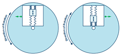
According to Watson (2016), a person moving north toward the outer edge of a rotating platform must increase the westward velocity component (blue arrows) to maintain a northbound course. The required acceleration is the Coriolis Acceleration. The green arrows indicate the force applied to the structure based on status of the resonating mass.
The author explains that, as shown in Figure 5, when the resonant mass moves towards the edge of the rotation, it is accelerated to the right and exerts a reaction force to the left on the frame. As it moves toward the center of rotation, it exerts a force to the right, as indicated by the green arrows. For Coriolis's truth, the frame containing the mass is tied to the substrate by springs at 90° in relation to the resonant motion.
With the resonant mass motion and with the surface to which the gyroscope is mounted, the mass and its structure experience Coriolis acceleration and are translated 90° of the vibratory motion. As the rate of rotation increases, so does the mass displacement and the signal derived from the corresponding capacitance change. It should be noted that the gyroscope can be placed anywhere on the rotating object and at any angle if the sensor axis is parallel to the axis of rotation (Watson 2016).
The sensor measures the displacement of the resonant mass due to the Coriolis effect through capacitive sensing elements attached to the resonator. A resonator is a device that exhibits resonance or resonant behavior, that is, it naturally oscillates at certain frequencies, called resonant frequencies, with greater amplitudes than at others. These elements are silicon beams interdigitated with two sets of silicon beams, stationary attached to the substrate, thus forming two nominally equal capacitors (Wikidata 2022; Watson 2016).
The resonator circuit senses the velocity of the resonant mass, amplifies, and drives the resonator while maintaining a well-controlled phase (or delay) with respect to the Coriolis signal path. The Coriolis circuit is used to detect the motion of the accelerometer frame with the mass drive direction and signal processing to extract the magnitude of the Coriolis acceleration and produce an output signal consistent with the input rotation rate. The displacement due to the angular rate induces a differential capacitance in this system. In practice, this acceleration is an extremely small signal (a unit of measurement of length equivalent to 10-10 m) of beam deflection. Therefore, it is extremely important to minimize cross-sensitivity to parasitic sources such as temperature, packaging stress, external acceleration, and electrical noise (Xia et al. 2014; Watson 2016).
The main source of error of the MEMS type gyroscope corresponds to the “bias”, which generates a linear growth over time, which can be corrected by calculating the variation generated in the device at rest (Aravena 2018; Shala & Rodriguez 2011).
5 Accelerometer
Used together with the gyroscope to define the rotation of the pulse is the accelerometer, which is an electromechanical device that measures the acceleration force. The most common type of accelerometer found in smartphones is the one that contains three axes and a capacitive principle. MEMS accelerometers are one of the simplest but also most applicable micro-electromechanical systems. They became indispensable in automobile industry, computer and audio-video technology (Andrejašic 2008).
The accelerometer is an electromechanical device with the purpose of measuring acceleration, unlike acceleration, which is measured between velocity and time, the function of the accelerometer is to measure the own acceleration which is the relation to another system in free fall, so that is linked to your sensation of weight, its function in IMU sensors is to measure speeds and distances covered. There are several types of accelerometers that can work from different physical effects such as resistive, magneto resistive, capacitive, piezoelectric and presents a wide range of acceleration values (Aroeira 2021).
The typical MEMS accelerometer is made up of a proof moving mass with plates that are attached via a mechanical suspension system to a frame of reference. Moving plates and fixed outer plates show the capacitors. The test mass deviation is measured using the capacitance difference. The test mass is fixed by springs (kS: constant spring) on the substrate. He can only move up and down. Moving and fixed plates build capacitors (Qazizada & Pivarčiová 2016).
Generally, when using an accelerometer, the developer seeks to extract the linear acceleration, this acceleration is only that applied to the sensor, discounting the acceleration due to gravity. This acceleration, depending on the device, can be measured in three dimensions, and if it weren't for its lack of precision, it could easily be used to measure speed and displacement (Fux 2008). When working with this linear acceleration, this is usually where the first problem is found, since the sensor has a dubious accuracy, and has its own x, y and z axes different from the Earth-relative axes, it is difficult to say precisely what intensity the gravitational force is applying on each of these sensor axes (Meneguzzi, Treis & Cendron 2016)
Accelerometers based on MEMS circuits generally use capacitance to measure acceleration. Its microstructure looks like a comb, having an external fixed assembly and a mass attached to a spring that is limited to moving along one direction. When an acceleration occurs, the mass moves and the capacitance is changed between the two plates, which will be measured and processed by the system circuit (Andrejašic 2008).
The basic operating principle behind this accelerometer is the mass and spring system. Springs, while within their linear region, are governed by Hooke's law, which says that the displacement of the spring is proportional to the applied force, that is, F=kx, where k is a constant inherent in the spring, measured in N/ m and x is the strain of the spring, measured in meters (Figure 6).
Another physical principle involved is Newton's second law, which relates force to mass and acceleration through the equation F=ma. Equalizing both equations give ma=kx, and therefore it can be seen that an acceleration a cause a displacement of the mass of x=(ma)/k, or, alternatively, if the mass has undergone a displacement x, it means that the mass is under an acceleration of a=(kx)/m. In this way the problem of measuring acceleration became a problem of measuring the displacement of a mass. Note that the accelerometer only measures acceleration along the spring. This is therefore a single-axis accelerometer. For each axis along which you want to measure acceleration, you need a system like this (UFPR Electric / Sensors Operating Principle 2022).
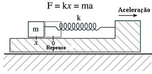
Figure 6
Mass system used to measure acceleration.
Source: UFPR Electric / Sensors Operating Principle (2022).
In the accelerometer there is a mass that is held by springs and has plates around it; when there is movement, there is an unbalance of the capacitive half-bridge, and the integrated circuit already processes the signal from the capacitors.
The accelerometer is related to the phenomenon of weight generated in a reference mass known by the measuring device. The main source of accelerometer error is the “bias”, which corresponds to the offset of the output signal with respect to its true value, this constantly generates an error in the position that has a quadratic growth over time (Shala & Rodriguez 2011; Regueiro 2014). The calibration of the accelerometer measurement can be performed periodically, measuring the variation of acceleration of the device at rest and considering the acceleration due to the movement of the Earth (Descamps-Vila, Pérez & Conesa 2013).
Accelerometers are considered inaccurate, and even static ones have significant noise. The problem with this noise is that it is random, and when we talk about integrating this noisy acceleration twice to get the displacement, there is a huge inaccuracy, since the accumulation of errors would quickly make the speed and displacement completely unreal (Crestani 2015). Some mechanisms are used to reduce this noise.
Usually filters are used, such as the Kalman filter. The Kalman filter is a simple algorithm that works recursively and dynamically, where you have a noisy dataset or with some type of interference and the algorithm tries to estimate the real value of that data (Fux 2008).
Regarding the quality of the accelerometer data, D'Elia et al. (2013) carried out a study evaluating the uncertainties in the accelerometer data and developed a methodology to determine the calibration parameters for this sensor.
6 Magnetometer
A magnetometer is a device for measuring the direction and intensity of magnetic fields. They are used in geophysics studies, for navigation, mineral prospecting, evaluation of interference in communications and so on. There are several types of magnetometers, among them there are vectors that measure the strength and direction of an Earth's magnetic field. In mobile devices, vector magnetometers are used to measure the component of the magnetic field in each direction relative to the spatial orientation of the device (Regueiro 2014; Shala & Rodriguez 2011).
Other sensors on the market use the magneto-resistive effect. These sensors use materials sensitive to the magnetic field, generally composed of Iron (Fe) and Nickel (Ne). Therefore, when these materials are exposed to the magnetic field, they change their resistance.
MEMS construction magnetometers use the resistive magneto effect or Hall effect to capture the magnetic fields, most of them use the Hall effect which consists of a conductive plate (Stuhler 2022).
Geomagnetic sensor (magnetometer) improves GPS results by capturing the magnetic field. More simply, it is said to act like a compass detecting the planet's magnetic north pole. It is used, for example, on the Google Maps platform when it identifies the user's current position.
The magnetometer used to measure the yaw angle corresponds to the magnetic azimuth, it varies as the device is moved around the “Z” axis, it can be calibrated to help the gyroscope data to improve the drift issue, but in some cases, when The magnetometer is built into the IMU, depending on the project, may present a disadvantage if the environment being used is surrounded by ferromagnetic metal, or by magnetic interference from electric motors, as they can affect the reading of the magnetic field (Android 2022; Stuhler 2022).
When we define the current that passes through it, electrons begin to flow from one side of the plate to the other, creating a flux, when approaching a magnetic field close to the plate, it will automatically interfere with the flow of electrons, deflecting them to one side of the plate, creating a positive and a negative side, when measuring between the two sides of the plate there will be a voltage that depends on the strength of the magnetic field and its direction (Stuhler 2022).
The main sources of errors in magnetometers are magnetic interference of the sensor and the presence of ferrous elements or material in the construction of the instrument. The error is estimated through long-term measurements on the device at rest (Regueiro 2014). Odenwald (2019) presented some experiments to evaluate the quality of the digital compass from smartphones, evaluating how the variation of the data obtained from the measured magnetic north occurs in different environments.
Azimuth angle measurement using the geomagnetic sensor is considered unreliable due to the distortion of the Earth's magnetic field by soft iron and hard iron caused by geomagnetic disturbances. Although many studies have been carried out to determine how to compensate for this distortion, most disturbances cannot be compensated for in places with extreme disturbances. In most cases, studies on omnidirectional azimuth have been carried out, and there are no studies to determine the accuracy of the result, which could not have been applied in a real situation (Oh & Kim 2020).
7 GNSS
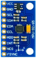
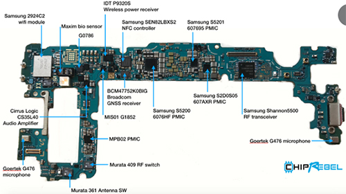
In the context of positioning by Global Navigation Satellite System (GNSS), the International Association of Geodesy (IAG), through sub-committee 4.1 (SC 4.1: Emerging positioning technologies and GNSS augmentation) linked to Commission 4 (Positioning and Applications), presents as one of its objectives research and development in low cost GNSS positioning systems, using smartphones. In Figure 7, you can see some sensors present in a specific model of smartphone, highlighted in the Figure is the GNSS sensor that has a few millimeters in size.
Gomes (2019) conducted a survey to assess the quality of GNSS positioning performed by smartphones. The author presents that in this innovative context, certain applications have emerged aimed at positioning accuracy that allow storing data in files in the universal RINEX format, making it possible to carry out post-processing and, consequently, the possible improvement in the positional accuracy obtained by the mobile device. The author also highlights that among the existing technological innovations in the context of positioning via smartphones, it is worth mentioning the use of modern dual-frequency GNSS sensors, capable of collecting information from multiple constellations (eg. GPS, GLONASS, Galileo, Bei Dou and QZSS) and multiple frequencies (eg L1/L5, B1, E1/E5).
Another study carried out along this line aimed to assess the feasibility of obtaining improved positioning accuracy with raw GNSS measurements using Precise Point Positioning (PPP), and positioning accuracy from selected devices newly available on the market (Aggrey et al. 2020).
Through a new Application Programming Interface (API) implemented in Android 7 (API level 24) and its successors, it is possible to access raw GNSS data, such as the information used in the calculation of pseudodistances, navigation messages, information from satellite clocks, carrier wave phase, among others (Gomes 2019).
By observing the great potential of this innovative methodology, the scientific community and companies in the field of geosciences have developed certain applications based on the modern API. The company Google made the first application available free of charge, called Gnss Logger, which makes it possible to store raw GNSS data in a specific format, enabling the analysis of this data in the GNSS Analysis app software, developed by the company Diggelen and Khider (2018).
8 Lidar Scanner
Historically, smartphones have integrated depth sensors and augmented reality. The first smartphone equipped with Time of Flight (ToF) camera and augmented reality features launched in the consumer market was in 2016. In 2020, an American company launched the iPad Pro 2020 and the iPhone 12 on the market with the presence of LiDAR sensors (Constantino et al. 2022).
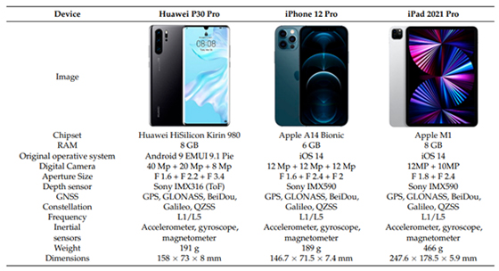
The term LiDAR scanner describes a new sensor that measures depth and detects objects in three dimensions. LiDAR sensor technology is widely used for various applications, however in 2020 it is the first time that this technology is used coupled with smartphones. It is important to emphasize that from a survey using a laser scanner, scans of hundreds and thousands of points are obtained for the 3D reconstitution of an environment or an object, which requires devices with a high operational capacity so that processing is possible and analysis of these data. In Figure 8 is possible to verify the specification of sensor embedded in these devices.
Many systems designers (whether developing self-driving cars, smartphones, or tablets) have been exploring ways to add “depth” information to pixels and colors captured by 2-D image sensors. LiDARs are being adopted by the automotive industry to detect and map distances of objects around highly automated vehicles, for example (Yoshida 2020).
In recent years, smartphones equipped with depth sensors have been launched in the consumer market. These sensors were advertised as “LiDAR scanners” for iOS devices and “time-of-flight depth cameras” (ToF cameras) for Android. Sensors were originally used to improve the quality of photos (e.g., improved camera focus, bokeh effect, etc.) and to enable augmented reality applications, but they proved suitable for other purposes (Constantino et al. 2022).
The LiDAR scanner used by smartphones features a specific technology used inside the unit to detect and measure depth. There are several technology options available to system designers for 3D surveying. They include stereo vision, structured light, and time of flight - the English term: Time of Flight (ToF). To make things even more complicated, ToF now comes in two types: indirect Time of Flight (iToF) and direct Time of Flight (dToF). iToF measures the phase shift, while dToF measures the direct time of flight (Figure 9).
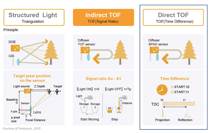
With the launch of the Laser sensor for smartphones, 3D detection has become more detailed with the adoption of a direct time-of-flight sensor. To date, Apple's iPad Pro is the only consumer product that uses dToF. Many smartphone vendors already use iToF to take better photos (ToF can blur the background in photos), but not dToF. The structured light method provides high depth accuracy, but its downside is the complex post-processing required to calculate pattern matching depth. In contrast, the advantage of the dTOF method is its ability to offer simple post-processing (Constantino et al. 2022).
Its challenge, however, is thought to be that it requires photodetectors with high sensitivity (such as single-photon avalanche diodes) and a form to measure time of flight with a small number of incident photons in a single measurement. So far, among 3D imaging methods, the iTOF method has been the most common. It provides high depth accuracy, simple post-processing and high spatial resolution using small photodetectors that are widely used in 2D image sensors. It is now using dToF for AR (Constantino et al. 2022).
The developed "LiDAR scanner" sensor consists of an emitter - a vertical cavity surface emission laser (VCSEL) from Lumentum and a receiver - near infrared (NIR) CMOS image sensor that makes direct measurement of time of flight developed by Sony.
Constantino et al. (2022) evaluated the performance of smartphone depth sensors (Time of Flight Camera (ToF) and Light Detection and Ranging (LiDAR) from Android (Huawei P30 Pro) and iOS (iPhone 12 Pro and iPAD 2021 Pro) to build a cloud of 3D points. The quality of point clouds was evaluated through visual analysis and using three specific characteristics: surface variation, planarity and omnivariance. Based on this approach, some problems with point clouds generated by smartphones were highlighted, such as splitting loss of planarity and drift problems of the inertial navigation system. Furthermore, it can finally be deduced that, in the absence of scanning problems, the accuracies achieved with this type of scanning are ~1 to 3 cm (Constantino et al. 2022).
The authors Constantino et al. (2022) also presented some studies that used LiDAR sensor for different kinds of application. For example, Spreafico et al. (2021) presented research on the large-scale 3D mapping capabilities of the iPad Pro's LiDAR sensor. Focusing on architectural research applications, Spreafico et al. (2021) scanned a scene consisting of an outside emergency escape ladder connected to a building. The point cloud captured with the iPad Pro showed an accuracy of 0.02 m and an accuracy of 0.04 m, which - importantly - is suitable for architectural mapping at a scale of 1:200. Another example is Riquelme et al. (2021), who used an iPhone 12 Pro to scan a mechanical excavation of 26 m Cretaceous marlstone and limestone rock face and rock discontinuities extracted from the point cloud.
9 Experiment
As previously mentioned, the orientation sensor is classified as a software sensor (Table 1), and serves to measure the degrees of rotation of the device along its three physical axes (x, y and z), as represented in Figure 1.
From the use of this sensor, it is possible to obtain the orientation angles, and these angles have a correspondence with the horizontal directions (and horizontal angles) and vertical angles measured with a total station. For comparison purposes, and to verify the accuracy of the data obtained with this software sensor, the experiment described below was performed.
Primarily, an application was developed using the sofware Android studio with the Kotlin programming language. This app allows the smartphone to display the corresponding value of the orientation angles measured with the smartphone. A base for the smartphone was also developed, which can be attached to the telescope of a total station, in order to verify the orientation angles measured with the total station, and the angles measured with the smartphone (Figure 10).
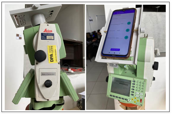
Figure 10
Developed base coupled to the total station.
Source: Authors (2022).
To carry out the experiments, a total station Leica TS15 model was used, which presents 1” of angular precision. It was used the smartphone model Xiomi Redmi 8, which has the sensors necessary to obtain angular information.
The smartphone was attached to the developed base, and angular measurements were taken with the smartphone and with the total station. The total station was rotated along its main axis, and then the total station telescope was rotated to obtain different vertical angles.
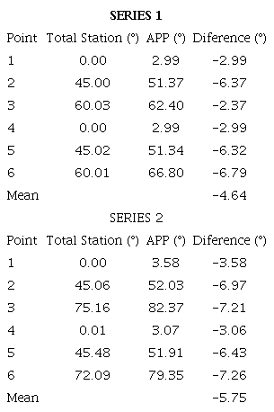
In Table 2 is possible to verify the vertical angles (pitch) measured with the total station and with the smartphone. Two series of readings were performed, varying the measured vertical angle between 0° and 75.16°.
Source: Authors.
It was observed that the average between the observed discrepancies was 4.64° in module in the first series of readings, and 5.75° in the second series of measurements for the vertical angles.
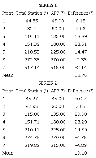
In Table 3 it is possible to verify the horizontal directions measured with the total station and with the smartphone. Two series of readings were performed, varying the measurements between 44.85° and 319.89°.
Source: Authors.
In Table 3, it is possible to observe that the average between the observed discrepancies was 10.76° in module in the first series of readings, and 10.10° in the second series of measurements for the horizontal directions.
Although the data in Tables 2 and 3 refer to angular measurements, it is observed that the discrepancies found are greater in relation to the horizontal directions. This occurs because the horizontal directions corresponding to the yaw angle are measured from the orientation sensor, which considers a combination of sensors as shown in Table 2. The gravity and magnetic field sensors are used especially for the determination of horizontal angle. So it is possible to infer that this angle is directly influenced by the magnetic field. Therefore, it presents a greater variation compared to the vertical angle (pitch).
It can be seen that the discrepancies between the values measured by the APP and the total station for the horizontal directions are greater at angles closer to 150°. These discrepancies have a similar behavior in the two series of measurements performed, increasing as the measured direction increases, and decreasing as it approaches the initial measured direction. Due to this, it can be observed that there is a systematic error in the measurements that needs to be treated. However, the causes of this systematic error in the measurements of the horizontal direction measured from this orientation sensor have not yet been investigated.
10 Final Considerations
With the data from different sensors presented, it is possible to obtain the orientation of the smartphone and it is possible to determine the coordinates and measurements of objects from these sensors. The data obtained still have limitations, but an adequate precision for certain types of application, as seen in detail in the types of sensors presented in this article.
One of the main applications for using these data from sensors is the planning of a monitoring network or a topographic survey. It can be done through applications that help the field survey in loco, and can be carried out from a previous visit to the study area, in which are evaluated the physical elements imposed in the place where the field work will be done. The development of tools to verify how and where the points of a monitoring network can be deployed, for example, can be done using mobile applications that use the sensors presented in this research. Thus, it could be analyzed if there is intervisibility between the points, the approximate location of where you want to implement the points of a geodetic monitoring network. Furthermore, it is possible to estimate the approximate values for the observations to be collected, necessary for the application of the concepts of error propagation to perform a pre-analysis of the geodesic network to be implemented.
The possibility of obtaining measurements in loco from mobile applications, planning a topographic survey based on measurements and previous data that can be collected for the purpose of surveying or even monitoring a certain area, facilitates field activities of a professional in the surveying area. It optimizes work, reduces costs and, depending on the purpose of the survey, avoids unnecessary field trips, since the needs for information related to the area under study can be met before carrying out the survey itself.
The gyroscope, accelerometer and magnetometer sensors allow to obtain the roll, pitch and yall angles, in relation to the equipment axes, presented in item 1 of this article. Using these sensors, is possible to obtain, for example, the angles of rotation, inclination and approximate azimuth for a given positioning of the smartphone. They are sensitive sensors, so they present inconsistencies in the measurements of angles, depending on several factors, such as: the brand and model of the sensor attached to the smartphone; external factors such as the temperature of the environment in which the measurement is being carried out; and the Earth's magnetic field (for the magnetometer).
Another sensor presented was the GNSS. From their development, the GNSS sensors began to receive signals from different constellations and different carrier waves, which increasingly contributed to an improvement in the positional quality provided by the devices. Furthermore, the possibility of obtaining the raw tracking data and performing the post-processing of them, opens a huge field of possibilities for the development of positioning tools. The accuracy of the data measured by these sensors and the possibilities regarding data processing and analysis varies from device to device.
The last sensor presented was the Lidar sensor. This sensor features state-of-the-art technology that allows obtaining, for example, measured distances from the device. Its development for use in smartphones was initially aimed at improving the quality of image sensors present in smartphones, with the possibility of developing augmented reality. The first smartphones coupled with these sensors appeared on the market in 2020, so it is a recent technology.
Research and investigations into the quality of all these types of sensors still need to be deepened. But it is known that they have enormous potential to improve the ability of smartphones to be a practical measurement tool for users.
An example of how orientation sensors can be tested is given in the last topic of this research, in which is possible to verify a comparison between the angles measured from sensors of a smartphone and the angles measured from a full station with high precision. It was verified that for the measurement of the vertical angles, it is possible to obtain discrepancies of the order of 5.2° in module. For the horizontal orientation measures, it was observed a systematic error that still needs to be investigated.
Despite these results, it is known that technological advancement in microelectronics is a process in continuous evolution, allowing the use of MEMS sensors for applications in the field of geosciences. With the development of laser scanner sensors for smartphones, it is an indication that will be possible to measure distances from tools developed for smartphones with sufficient quality for various applications.
11 References
Aggrey, J., Bisnath, S., Naciri, N., Shinghal G. & Yang, S. 2020, 'Multi-GNSS precise point positioning with next-generation smartphone measurements', Journal of Spatial Science, vol. 65, no. 1, pp. 79-98, DOI:10.1080/14498596.2019.1664944.
Andrejašic, M. 2008, 'Mems accelerometers', Seminar, University of Ljubljana, Ljubljana, viewed 28 November 2022, < 2008, 'Mems accelerometers', Seminar, University of Ljubljana, Ljubljana, viewed 28 November 2022, https://faculty.uml.edu/xwang/16.541/2010/MEMS_accelerometers.pdf>.
Android 2022, Visão geral dos sensores, viewed 2 July 2022, <Android 2022, Visão geral dos sensores, viewed 2 July 2022, https://developer.android.com/guide/topics/sensors/sensors_overview?hl=pt-br>.
Aravena, C.A.A. 2018, 'Desenvolvimento de aplicação para posicionamento indoor por meio das redes wifi em ambientes internos', Master Thesis, Universidade Federal do Paraná, Curitiba, viewed 2 July 2022, < 2018, 'Desenvolvimento de aplicação para posicionamento indoor por meio das redes wifi em ambientes internos', Master Thesis, Universidade Federal do Paraná, Curitiba, viewed 2 July 2022, https://hdl.handle.net/1884/60080>.
Aroeira, C. 2021, Types of Accelerometers, viewed 28 November 2022, < 2021, Types of Accelerometers, viewed 28 November 2022, https://www.dmc.pt/en/tipos-de-acelerometros>.
Crestani, T. 2015, 'Desenvolvimento de API para rastreamento híbrido de dispositivos móveis em ambientes internos', Undergraduate Thesis, Instituto Federal Catarinense, Videira.
Conti, G., Ribeiro, S.R.A. & Dias, A.H. 2015, 'Arquitetura de um sistema de informação geográfica mobile para coleta de dados geográficos baseados em conceitos de cloud computing e banco de dados NoSQL', X Congresso Brasileiro de Agroinformática, 21-23 October, viewed 28 November 2022, < 2015, 'Arquitetura de um sistema de informação geográfica mobile para coleta de dados geográficos baseados em conceitos de cloud computing e banco de dados NoSQL', X Congresso Brasileiro de Agroinformática, 21-23 October, viewed 28 November 2022, https://www.researchgate.net/publication/324482003_Arquitetura_de_um_sistema_de_informacao_geografica_mobile_para_coleta_de_dados_geograficos_baseados_em_conceitos_de_cloud_computing_e_banco_de_dados_NoSQL>.
Constantino, D., Vozza, G., Pepe, M. & Alfio, V.S. 2022, 'Smartphone LiDAR Technologies for Surveying and Reality Modelling in Urban Scenarios: Evaluation Methods, Performance and Challenges',Applied System Innovation, vol. 5, no. 4, 63, DOI:10.3390/asi5040063.
Daponte, P., De Vito, L., Picariello, F. & Riccio, M. 2013, 'State of the art and future developments of measurement applications on smartphones', Measurement, vol. 46, no. 9, pp. 3291-307, DOI:10.1016/j.measurement.2013.05.006.
D'Elia, M.G., Giudice, A., Graditi, G. & Paciello, V. 2013 'Measurement uncertainty on smart phone', IEEE International Conference on Computational Intelligence and Virtual Environments for Measurement Systems and Applications, pp. 144-9, DOI:10.1109/CIVEMSA.2013.6617411.
Descamps-Vila, L., Pérez, A & Conesa, J. 2013, 'Integración de un sistema de posicionamiento Indoor en aplicaciones SIG para dispositivo movil', VIIJornada de SIG libre, viewed 25 September 2022, < 2013, 'Integración de un sistema de posicionamiento Indoor en aplicaciones SIG para dispositivo movil', VII Jornada de SIG libre, viewed 25 September 2022, https://dugi-doc.udg.edu/bitstream/handle/10256/7651/29Art-Integracion.pdf?sequence=1>.
Diggelen, F.V. & Khider, M. 2018, GNSS Analysis Tools from Google, Inside GNSS, viewed 13 December 2022, < 2018, GNSS Analysis Tools from Google, Inside GNSS, viewed 13 December 2022, https://insidegnss.com/gnss-analysis-tools-from-google>.
Geekfactory 2022, Geek Factory, viewed 10 August 2022, <Geekfactory 2022, Geek Factory, viewed 10 August 2022, https://www.geekfactory.mx/>.
Fux, S. 2008, 'Development of a planar low-cost Inertial Measurement Unit for UAVs and MAVs', Master Thesis, Swiss Federal Institute of Technology Zurich, Zurich.
Galaxy S10 teardown 2022, Samsung Galaxy S0 teardown, viewed 04 October 2022, <Galaxy S10 teardown 2022, Samsung Galaxy S0 teardown, viewed 04 October 2022, https://www.chiprebel.com/galaxy-s10-teardown/>.
Grewal, M. & Andrews, A. 2010, 'How good is your gyro', IEEE Control Systems Magazine, vol. 30, no. 1, pp. 12-86, DOI:10.1109/MCS.2009.935122.
Gomes, A. 2019, 'Avaliação da qualidade posicional de um sensor gnss de dupla frequência presente em um smartphone sob diferentes cenários e métodos de posicionamento', Master Thesis, Universidade Federal do Paraná, Curitiba, viewed 4 October 2022, < 2019, 'Avaliação da qualidade posicional de um sensor gnss de dupla frequência presente em um smartphone sob diferentes cenários e métodos de posicionamento', Master Thesis, Universidade Federal do Paraná, Curitiba, viewed 4 October 2022, https://hdl.handle.net/1884/66320>.
Hwang, J., Yun, H., Suh, Y., Cho, J. & Lee, D. 2012, 'Development of an RTK-GPS positioning application with an improved position error model for smartphones', Sensors, vol. 12, no. 10, pp. 12988-300, DOI:10.3390/s121012988.
IDC 2020, Smartphone Market Share - OS Data Overview, viewed 15 May 2020, <IDC 2020, Smartphone Market Share - OS Data Overview, viewed 15 May 2020, https://www.idc.com/promo/smartphone-market-share/os>.
Kuhlmann, T., Garaizar, P. & Reips, U. 2021, 'Smartphone sensor accuracy varies from device to device in mobile research: the case of spatial orientation', Behavior Research Methods, vol. 53, no. 1, pp. 22-33, DOI:10.3758/s13428-020-01404-5.
Meneguzzi, L., Treis, R.F. & Cendron, M.M. 2016, 'Utilização de giroscópio e acelerômetro para identificação de movimentação em ambientes tridimensionais', V Feira de iniciação científica e extensão,15-16 September, pp. 1-9, viewed 4 October 2022, < 1-9, viewed 4 October 2022, http://videira.ifc.edu.br/fice/wp-content/uploads/sites/27/2016/09/10-Artigo-UTILIZA%C3%87%C3%83O-DE-GIROSC%C3%93PIO-E.pdf >.
MIT 2020, MIT app inventor, viewed 10 November 2020, <MIT 2020, MIT app inventor, viewed 10 November 2020, http://appinventor.mit.edu>.
Odenwald, S. 2019, 'Smartphone sensors for citizen science applications: Radioactivity and magnetism', Citizen Science: Theory and Practice, vol. 4, no. 1, 18, DOI:10.5334/cstp.158.
Oh, J. & Kim, M. 2020, 'Method to determine initial aiming azimuth accuracy using acceleration, gyroscope, and geomagnetic sensors', ICT Express, vol. 6, no. 2, pp. 117-20, DOI:10.1016/j.icte.2019.10.004.
Oliveira, A.L., Vianna, L.S., Nascimento, B.R., Vita Neto, M.L. & Santos, M.G.A. 2014, 'Um estudo sobre o sistema operacional Android', Revista de trabalhos acadêmicos-campus Niterói, no. 7, pp. 1-11, viewed 10 November 2022, < 1-11, viewed 10 November 2022, http://revista.universo.edu.br/index.php?journal=1reta2&page=article&op=view&path%5B%5D=1182&path%5B%5D=886>.
Passaro, V.M.N., Cuccovillo, A., Vaiani, L., De Carlo, M. & Campanella, C.E. 2017, 'Gyroscope technology and applications: a review in the industrial perspective', Sensors, vol. 17, no. 10, pp. 2284-317, DOI:10.3390/s17102284.
Peres, F.F.F., Scheer, S., Faria, É.F. & Vian, D. 2015, 'Realidade aumentada para o acesso à instrumentação da barragem de Itaipu', XXXSeminário Nacional de Grandes Barragens, 12-14 May, Foz do Iguaçu, pp. 1-9, viewed 15 July 2022, < 1-9, viewed 15 July 2022, https://docplayer.com.br/2200630-Realidade-aumentada-para-o-acesso-a-instrumentacao-da-barragem-de-itaipu.html>.
Qazizada, M.E. & Pivarčiová, E. 2016, 'Mobile robot controlling possibilities of inertial navigation system', Procedia Engineering, vol. 149, pp. 404-13, DOI:10.1016/j.proeng.2016.06.685.
Regueiro, C.S. 2014, 'Error en el posicionamiento indoor en dispositivos móviles', Undergraduate Thesis, Universitat Oberta de Catalunya, Catalunya, viewed 15 July 2022, < 2014, 'Error en el posicionamiento indoor en dispositivos móviles', Undergraduate Thesis, Universitat Oberta de Catalunya, Catalunya, viewed 15 July 2022, http://hdl.handle.net/10609/34081>.
Wikidata 2022, Resonator, viewed 28 November 2022, <Wikidata 2022, Resonator, viewed 28 November 2022, https://www.wikidata.org/wiki/Q349669>.
Riquelme, A., Tomás, R., Cano, M., Pastor, J.L. & Jordá-Bordehore, L. 2021, 'Extraction of discontinuity sets of rocky slopes using IPhone-12 Derived 3DPC and Comparison to TLS and SfM Datasets', IOP Conference Series: Earth and Environmental Science, vol. 833, no. 1, 012056, DOI:10.1088/1755-1315/833/1/012056.
Sampaio, L.F., Ito, A.L.B., Veiga, L.A.K., Alves, S.S.O., Carvajal, F.A.R. & Medeiros, L.I.B. 2022, 'Feasibility of using data from sensors embedded in smartphones to measure angles and distances', Revista Brasileira de Cartografia, vol. 74, no. 4, pp. 805-18, DOI:10.14393/rbcv74n4-65814.
Shala, U. & Rodriguez, A. 2011, 'Indoor Positioning using Sensor- fusion in Android Devices', Master Thesis, Kristianstad University, Sweden, viewed 4 October 2022, < 2011, 'Indoor Positioning using Sensor- fusion in Android Devices', Master Thesis, Kristianstad University, Sweden, viewed 4 October 2022, http://www.diva-portal.org/smash/record.jsf?pid=diva2%3A475619&dswid=-6119>.
Spreafico, A., Chiabrando, F., Losè, L.T. & Tonolo, F.G. 2021, 'The Ipad Pro Built-In LIDAR sensor: 3d rapid mapping tests and quality assessment', International Archives of the Photogrammetry, Remote Sensing and Spatial Information Sciences, vol. 43, pp. 63-9, DOI:10.5194/isprs-archives-XLIII-B1-2021-63-2021.
Stuhler, J. 2022, 'Utilização de MEMS ((Micro-Electro-Mechanical Systems-sistemas microeletromecânico) para aplicações de circuitos de baixo custo de movimentação e sensoriamento', Metodologias e Aprendizado, vol. 5, pp. 82-91, DOI:10.21166/metapre.v5i.2696.
UFPR Electric / Sensors Operating Principle 2022, Acelerômetros, viewed 4 October 2022, <UFPR Electric / Sensors Operating Principle 2022, Acelerômetros, viewed 4 October 2022, http://www.eletrica.ufpr.br/edu/Sensores/1999/joao/index.htm>.
Weinberg, H. 2011, 'Gyro mechanical performance: the most important parameter', Analog Devices, pp. 1-5, viewed 26 October 2022, < 1-5, viewed 26 October 2022, https://www.analog.com/en/technical-articles/gyro-mechanical-performance.html#:~:text=The%20most%20significant%20are%20usually,(or%20g2%20sensitivity)>.
Watson, J. 2016, Mems gyroscope provides precision inertial sensing in harsh, high temperature environments, viewed 8 May 2021, < 2016, Mems gyroscope provides precision inertial sensing in harsh, high temperature environments, viewed 8 May 2021, https://www.analog.com/media/en/technical-documentation/tech-articles/MEMS-Gyroscope-Provides-Precision-Inertialensing-in-Harsh-High-Temps.pdf>.
Xia, D., Yu, C. & Kong, L. 2014, 'The development of micromachined gyroscope structure and circuitry technology', Sensors, vol. 14, no. 1, pp. 1394-473, DOI:10.3390/s140101394.
Yoshida, J. 2020, Breaking Down iPad Pro 11’s LiDAR Scanner, viewed 28 September 2022, < 2020, Breaking Down iPad Pro 11’s LiDAR Scanner, viewed 28 September 2022, https://www.eetimes.com/breaking-down-ipad-pro-11s-lidar-scanner>.
Funding information
Data availability statement
Author notes
E-mail:liviafariasampaio@gmail.comE-mail:kngveiga@gmail.comE-mail:samir.alves@eng.uerj.br
Conflict of interest declaration