Mecánica
PID Control for a Two-Axis Orientable Solar Panel System
Control PID para un Sistema de Panel Solar Orientable de Dos Ejes

PID Control for a Two-Axis Orientable Solar Panel System
Scientia Et Technica, vol. 24, no. 4, pp. 581-589, 2019
Universidad Tecnológica de Pereira
Received: 08 August 2019
Accepted: 19 December 2019
Abstract: Orientable solar panel systems (OSPS) greatly improve its performance, based not only on the orientation motion at the right time along the day but also using a good motion strategy to describe that rotation. The control of a two degree-of-freedom OSPS was simulated for a control scheme that combines Proportional, Integral and Derivative actions with a computed torque control inner loop. The latter controller calculates the torques at the joints. Two plants of the dynamic model of the OSPS were evaluated: analytical and Simmechanics. Three case motions were simulated: random, to a sef position, and end-of-the-day cycle. Controller gains were set by using the sustained oscillation Nichols-Ziegler second syntonization method. It was found that in order to save energy along the motion the non-underdamped behavior is required. This is attained by setting the integral component gain to zero. Very small maximum theoretical position errors of the azimuth and elevation position angles suggest that the combination Proportional Derivative combined with Computed Torque Control scheme is satisfactory for controlling the OSPS motion along day.
Keywords: Nichols-Ziegler, 2nd method, Orientable solar panel, PID-CTC.
Resumen: Los sistemas solares de paneles orientables mejoran grandemente su desempeño, basado no solamente en el movimiento en el momento indicado, sino también una adecuada estrategia de movimiento para describir esa rotación. El control de un Sistema de Panel Solar Orientable de dos grados de libertad fue simulado para un esquema de control que combina acciones Proporcional, Integral y Derivativa con un lazo interno de control de par computado. Este lazo interno de control permite el cálculo de torques en las juntas. Fueron evaluadas dos plantas del modelo dinámico del Panel Solar Orientable: analítica y Simmechanics. Tres casos de movimiento fueron simulados: aleatorio, a una posición segura y final del ciclo diario. Las ganancias del controlador se hallaron usando la oscilación sostenida del segundo método de sincronización Nichols-Ziegler. Para ahorrar energía durante el movimiento, se requiere movimiento no subamortiguado, obtenido mediante la anulación de la componente integral del controlador. Errores de posición teóricos muy pequeños para ángulos de elevación y azimut, sugieren que el esquema Proporcional Dreivativo con Control de Torque Calculado es satisfactorio para controlar el movimiento del panel durante el día.
Palabras clave: Nichols-Ziegler, 2nd método, Panel solar orientable, PID-CTC.
I. INTRODUCTION
Tracking motion of Orientable Solar Panel Systems (OSPS) have gained attention during the last decade due to its effect on the OSPS efficiency. Movable solar panel systems have been reported to overcome the efficiency of fixed solar panel systems [1]. However, Eke and Senturk showed that efficiency improves up to 40% more when the system is comprised of two movable axis (azimuth and elevation) [2]. They were compared efficiencies of fixed panel systems with double-axis motion OSPS where the perpendicularity of the panel to the sunrays was kept.
Studies of motion for the solar panel of OSPS are reported even since 2011. Usta et al. [3] reported the comparison of fuzzy logic control and Proportional Integral (PI) control strategies with Matlab/Simulink for simulation. They found that fuzzy logic approach provides panel motion with less overshoot. However, the study was only performed for a system with one single axis. Later, Alexandru [4] (2013) also proposed a closed-loop control strategy, this time for dual axis. He considered the tracking motion command as a perturbation and the controller tuning was achieved by using parametric optimization process. One year later, Ozerdem and Shahim [5] implemented a Proportional Integral Derivative (PID) control strategy in a basic two axis prototype controlled by Arduino/Matlab/Simulink. They used light dependent resistances and a filter coefficient for limit positions. Their comparison of point to point motion versus PID action proved the latter more efficient.
In 2015, an advanced PID controller was developed by Gregor et al. [6] for grid (arrays) OSPS’s, with a modification of the regular PID additive control action. Kiyak and Gol [7] showed in 2016 that the fuzzy logic controller is more efficient that PID controller. Similarly to [3], the report was limited to a single axis motion system. Also in 2016, Kumar and Sharma [8] simulated the PID control strategy addressing maximum voltage in a single axis solar system. However, the OSPS was considered as an electric circuit without providing modelling of the physical system. In the same year, Oladayo and Titus [9] combined a PID controller (tuned using fuzzy logic) with an Internal Model Control-IMC for good disturbance rejection. They showed an improvement in the system speed response, but the simulation was limited to one axis.
Separately, Dwivedi and Saket [10] (2017) improved the peak power performance in the simulation of a single axis panel using PID control strategy. In the same year, Safan et al. [11] assessed the performance of an OSPS by using PID control strategy. Their approach was Multiple Input Multiple Output (MIMO) to control both axis (azimuth and elevation). The position feedback was obtained by implementing the sun position algorithm. A more recent work (2018), presents the combination of quadratic regulator technique to achieve a robust PID controller of a single axis OSPS [12]. They add the compensating pole to the quadratic regulator method in order to facilitate the PID tuning of the single axis control.
In this paper, two plants: analytical and Simmechanics (CAD) of the same OSPS are simulated for three cases of motion during the day. These cases are: random motion, motion to a secure position (sudden wind), and going to rest position. Plants were controlled with the same PID controller, whose gains were found with the Nichols-Zieglert second method. Tuning and simulation were carried out in Simulink (Matlab). The Computed Torque Control-CTC complemented the PID controller for calculating the torque required at the acted joints. Results are discussed by analyzing the azimuth and elevation position angles. In order to simplify and generalize analysis, the plant model is taken as an open chain two degrees-of-freedom (2-DOF) serial manipulator. This approach eases previous kinematic and dynamic analyses, and let using control strategies formulation available for serial manipulators [13,14,15]. Proven the performance improvement when panel orientation changes while kept perpendicular to the sunrays [16], this work brings a control strategy for a Colombian geographic location case.
II. MATERIALS AND METHODS
A. Kinematics
Figure 1 depicts the ground or element 0, the element 1 for azimuth motion labeled as joint angle θ1, and element 2 for elevation motion, joint angle θ2. In the shown representation, the solar panel is the open manipulator working tool. The transformation matrix, 0A2, shown in (Ec.1) [17] relates the ground element (or element 0) with the tool (panel) or element 2. Denavit-Hartenberg parameters notation [18] was followed to set (Ec.2), where ci: cosine of the joint angle θi; si: sine of the joint angle θi; a2: link distance for element 2; and d1: offset distance for element 1, as illustrated in Fig. 2. In this figure, three coordinate systems are introduced. They are the {0} coordinate system to label the fixed right axis reference system {x0-y0-z0}; {1} for the azimuth reference system {x1-y1-z1} and {2} for the elevation reference system {x2-y2-z2}.
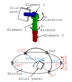
Fig. 1.
Azimuth and elevation motions in the 2-DOF open loop serial manipulator modeling the OSPS.
Autor
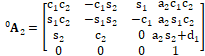 (1)
(1)Fig. 2 depicts the azimuth and elevation motion of the panel. Each element has a reference system, Fig. 1.b: fixed (inertial) {x0-y0-z0} or {0}, movable reference system {x1-y1-z1} or {1} for the azimuth motion, and local reference system {x2-y2-z2} or {2} for the elevation motion. The latter element is attached to the panel and the securing structure elements.

Fig. 2.
Simplified Denavit-Hartenberg parameters for the 2-DOF open loop serial manipulator modeling the OSPS.
Autor
B. Dynamic Model
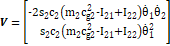
Stating the dynamic equation of a manipulator allows relating applied forces at the actuated joints with the expected motion [15]. The dynamics for the 2-DOF OSPS will follow the model proposed summarize in (Ec.2) and developed in [19] through Lagrange-Euler formulation, where τi: torque at joint i; m2: mass of OSPS element 2; ci: cosine of joint angle θi; si: sine of joint angle θi;  : angular velocity of element i or joint i velocity;
  : angular acceleration of joint i or joint acceleration; g: gravity (9.81m/s2); cg2: coordinate of the center of gravity for element 2; Iij: element corresponding to the i-th row and j-th column of the system inertia matrix.
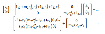 (2)
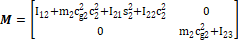
(2)(Ec.2) is the explicit form of the direct dynamics analysis of the OSPS where the joints responses are found, as written in (Ec.3) in compact form, where:  : joint acceleration vector, τ: applied torque vector at the joints; M: OSPS mass matrix: V: centrifugal and Coriollis forces vector; G: vector of torque due to gravity effect. By inspection from (Ec.2) and (Ec.3), the terms τ, M, V, and G are as given in (Ec.4), (Ec.5), (Ec.6), (Ec.7) and (Ec.8), respectively. As for the inverse kinematics formulation, the acceleration forces will depend on the acceleration vector, found as written in (Ec.9) [14, 15].
 (3)
(3)
 (4)
(4)
 (5)
(5)
 (6)
(6)
 (7)
(7)
 (8)
(8)
 (9)
(9)C. PID Control
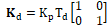
The classical Proportional Integral Derivative (PID) control strategy is shown in Fig. 3, where the reference or desired position, velocity and acceleration are labeled as qd,  and
and  , respectively, given by qd =[θ1 θ2]T (θ1: azimuth position angle, and θ2: elevation position angle). Kp, Ki and Kd are 2x2 diagonal gain matrixes that stand for the proportional, integral and derivative control actions, respectively. There are three compensators in the scheme. The gravity compensator G would compensate the torque at the joints due to the mobile parts weight. The inertia compensator M would compensate the effect of the inertia, and the velocity compensator V would do it for the centrifugal forces effect since there are no Coriolis terms. The three compensators make the contribution for the torque at the joints, τ, leading to a combined Computed Torque Control-CTC strategy to govern the motion of the OSPS panel. The main advantage of the technique is the high tracking accuracy, low feedback and low energy consumption [19]. The Simulink general control model is shown in Fig. 4, where the block “Solar Tracker” is the OSPS plant. In order to facilitate results comparison, one plant is from the analytical model widely explained in [20], while the other plant is a Simmechanics block created from a SolidWorks CAD model, see also [21]. Figure 5 depicts the Simulink controller block configuration. The Simulink block model for the dynamic analytical model in (Ec.2) can be consulted in [20], while the plant created in Simmechanics is depicted in Fig. 6.
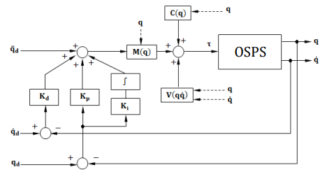
Fig. 3.
PID control with CTC scheme for the OSPS.
Autor

Fig. 4.
General control law Simulink block model.
Autor

Fig. 5.
Exploded controller.
Autor
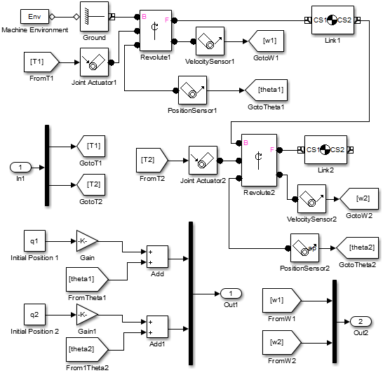
Fig. 6.
SimMechanics model of the plant inserted in the Simulink file.
Autor
III. RESULTS AND DISCUSSION
A. Illustrative Case
For the case in this report, the parameter values are d1=355mm, d2=0mm, a1=0mm, a2=91mm, α1=90°, α2=0°. The location of the OSPS system is chosen at Universidad del Atlántico (Puerto Colombia, Colombia): latitude 11.0159731, longitude -74.8746478. The date of the study case is January 1st, 2017. Three motions are considered with daytime and initial and final positions, see Table 1. The data was generated using www.sunearthtools.com [22]. Numerical values to feed the analytical model in (Ec.2) are given in Table 2.

Autor

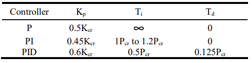
B. Ziegler-Nichols 2nd Syntonization Method
Initial gain matrix values for the PID controller will be found with the Ziegler-Nichols second syntonization method [23]. In this approach, both integral and derivative gains are made cero. Proportional gain is raised up to a critical point where the system output exhibits sustained oscillation. This proportional gain value is labeled as the critical proportional gain Kcr. The period of the oscillations, Pcr, and the critical proportional gain are used to find the proportional scalar gain Kp, the integral time Ti and the derivative time Td, with the equations in Table 3 for each PID case. Later, derivative, integral and proportional gain matrixes, Ki, Kd and Kp are found with (Ec.10), (Ec.11) and (Ec.12), respectively.
Autor
 (10)
(10)
 (11)
(11)
 (12)
(12)Case 1 (random motion) in Table 1 is analyzed. The Simulink model plant is used to raise the proportional gain from cero for both joints with the analytical plant. There were found the same values for both critical gains: Kcr1=10 and Kcr2=10, for joints 1 and 2, respectively, as seen in Fig. 7, where the sustained oscillations for both joints are displayed, with the same critical period Pcr1=2 and Pcr2=2, for joints 1 and 2, respectively. Table 4 contains the parameters obtained from Table 3 (Case 1-Random motion). By-inspection tuning of the gains was performed in Simulink model until an overdamped output is reached. Output is established as the joint orientation angles, θ1 and θ2. As a designer choice, underdamped behavior is not desirable since energy is wasted during the oscillations. By simplicity, the same gains are kept for both joints. It is noticed how when the derivative gain is raised and the integral gain is set to cero, that the system output presents the desired overdamped behavior. The same gain values are to be used in the three cases. From Fig. 8, the tuning gains yield Kp=20; Ki=0; Kd=10, for desired overdamped exhibit. These gains are used for the upcoming results.

Autor
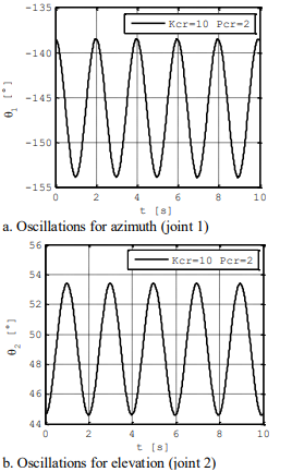
Fig. 7.
Sustained oscillations references with Kcr=10 and Pcr=2 for a. Azimuth joint (joint 1), b. Elevation joint (joint 2).
Autor
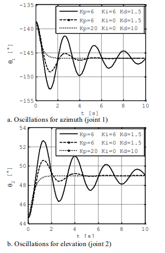
Fig. 8.
Ziegler-Nichols 2nd syntonization method gains tuning with Simulink for: a. Azimuth (Joint 1) and b. Elevation (Joint 2).
Autor
C.Comparison
Figure 9 depicts the position angles for azimuth (joint 1) and elevation (joint 2) for case 1 in Table 1. Torques at the joints, for the same case, are depicted in Fig. 10. Similarly, results for case 2 in Table 1 are presented in Figs. 11 and 12, for join angles and torques, respectively.
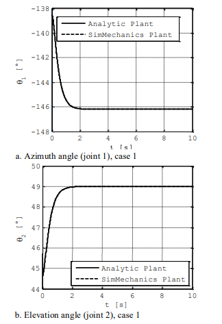
Fig. 9.
Joint angles for case 1: a. Azimuth (joint 1), b. Elevation (joint 2).
Autor
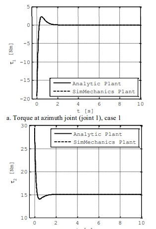
Fig. 10
Joint torques for case 1: a. Azimuth (joint 1), b. Elevation (joint 2).
Autor
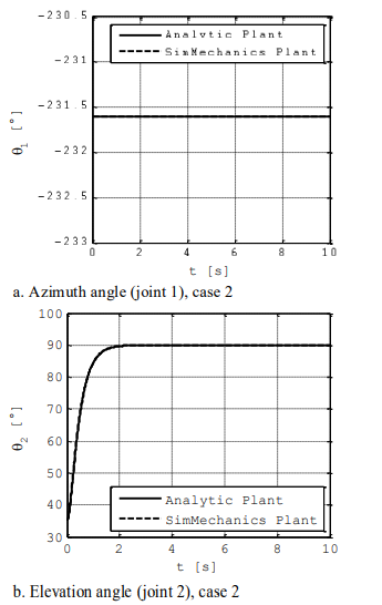
Fig. 11.
Joint angles for case 2: a. Azimuth (joint 1), b. Elevation (joint 2).
Autor
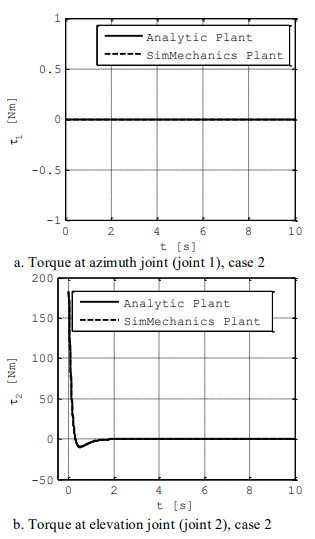
Fig. 12.
Joint torques for case 2: a. Azimuth (joint 1), b. Elevation (joint 2).
Autor
Figures 13 and 14 show the results for joint angles and torques for case 3 (Table 1), respectively.

Fig. 13.
Joint angles for case 3: a. Azimuth (joint 1), b. Elevation (joint 2).
Autor
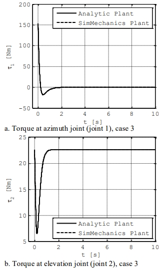
Fig. 14.
Joint torques for case 3: a. Azimuth (joint 1), b. Elevation (joint 2).
Autor
In all cases, results are considered satisfactory, since maximum theoretical joint position error are very small, as seen in Table V. Only for case 2 “Moving to a safe position”, the elevation angle (joint 2) –Fig. 13.b- there is a small different about 1 sec of simulation. This occurs due to the action of a random “wind”. Good performance is observed in other two cases of regular motion during the day. Results suggest that the control strategy is acceptable at the theoretical stage.

Autor
IV. CONCLUSIONS
A control strategy that combines PID gains and CTC compensation was evaluated for a modelled OSPS plant. Proportional, integral and derivative matrix gains were built using a single gain value that could satisfactorily control both azimuth and elevation joint motions. A Simulink block was used for identifying a critical period and a critical gain, according to the Ziegler-Nichols method, in order for further calculation of the PID gains. Input reference was modelled as step function. Gains tuning was also performed in the Simulink model for simulations of an OSPS system located at Puerto Colombia (Atlántico, Colombia) on January 1st, 2017. Three motion cases were considered: random motion, motion to a safe position and end-of-cycle motion. It was found that the integral gain component is not required for the system to exhibit overdamped behavior in each joint motion, leading to PD control type. The CTC block calculated the required torque to apply on each joint of the OSPS. Joint angle outputs were practically identical when using either the analytical plant or the Simmechanics model. Although satisfactory results were obtained, other control techniques can be applied by using the open robot modelling here presented.
REFERENCES
[1] P. Deepthi and D. Ranjitha, “Comparison of efficiencies of single-axis tracking system and dual-axis tracking system with fixed mount”, International Journal of Engineering Science and Innovative Technology, vol. 2, no. 2, pp. 425-430, March 2016.
[2] R. Eke, and A. Senturk, “Performance comparison of a double-axis sun tracking versus fixed PV system,” Solar Energy, vol. 86, no. 9, pp. 2665–2672, 2012. DOI: 10.1016/j.solener.2012.06.006
[3] M. Usta, Ö. Akyazi and Ï. Altaş, “Design and performance of solar tracking system with fuzzy logic controller”, in Proc. of International Advanced Technologies Symposium, Elazığ, Turkey, May 16-18, 2011, pp. 331–336.
[4] C. Alexandru, “A novel open-loop tracking strategy for photovoltaic systems,” The Scientific World Journal, vol. 2013, p. 12, 2013. DOI: 10.1155/2013/205396
[5] O. Ozerdem and A. Shahim, “A PV solar tracking system controlled by Arduino/Matlab/Simulink”, International Journal on “Technical and Physical Problems of Engineering”, vol. 24, no. 6(4), pp. 5-10, Dec 2014.
[6] R. Gregor, Y. Takase, J. Rodas, L. Carreras, D. Gregor and A. López, “Biaxial solar tracking system based on the MPPT approach integrating ICTs for photovoltaic applications”, International Journal of Photoenergy, 10 p, 2015. DOI: dx.doi.org/10.1155/2015/202986
[7] E. Kiyak, and G. Gol, “A comparison of fuzzy logic and PID controller for a single-axis solar tracking system,” Renewables: Wind, Water, and Solar, vol. 3, no. 7, 14 p, 2016. DOI: 10.1186/s40807-016-0023-7
[8] N. Kumar, and N. Sharma, “Improve performance of PV system by PID controller,” Int. J. of Science, Engineering and Technology, vol. 4, no. 1, pp. 227-232, 2016.
[9] B. Oladayo, and A. Titus, “Development of solar tracking system using IMC-PID controller,” American J. of Engineering Research, vol. 5, no. 5, pp. 135-142, 2016.
[10] L. Dwivedi, and R. Saket, “Improve efficiency of photovoltaic (PV) system based by PID controller,” Int. Research Journal of Engineering and Technology, vol. 4, no. 5, pp. 2273-2277, May 2017.
[11] Y. Safan, S. Shaaban, and A. El-Sebah, “Hybrid control of a solar tracking system using SUI-PID controller,” in Proc. of Sensors Networks Smart and Emerging Technologies (SENSET), Beirut-Lebanon, Sept. 12-14, 2017. DOI: 10.1109/SENSET.2017.8125035
[12] S. Hanwate, and Y. Hote, “Design of PID controller for sun tracker system using QRAWCP approach,” Int. J. of Computational Intelligence Systems, vol. 11, pp. 133-145, 2018. DOI: doi.org/10.2991/ijcis.11.1.11
[13] L. Tsai, Robot analysis, the mechanics of serial and parallel manipulators, New York, NY, USA: John Wiley and Sons, 1999.
[14] R. Jazar, Theory of applied Robotics, Springer: New York: Springer, 2007.
[15] M. Spong, S. Hutchinson, and M. Vidyasagar, Robot dynamics and control, 2nd ed., New York, NY, USA: Wiley, 2004.
[16] M. Koussa, M. Haddadi, D. Saheb, A. Malek, and S. Hadji, “Sun tracker systems effects on flat plate photovoltaic PV systems performance for different sky states: A case of an arid and hot climate,” Energy Procedia, vol. 18, pp. 839–850, 2012. DOI: 10.1016/j.egypro.2012.05.098
[17] C. Crane, and J. Duffy, Kinematic analysis of robot manipulators, New York, NY, USA: Cambridge University Press, 2008.
[18] J. Denavit, and R. Hartenberg, “A Kinematic notation for lower-pair mechanisms based on matrices,” J. Applied Mechanics, vol. 22, pp. 215–221, 1955.
[19] R. Islam, J. Iqbal and Q. Khan, "Design and comparison of two control strategies for multi-DOF articulated robotic arm manipulator", Control Engineering and Applied Informatics, vol. 16, no. 2, pp. 28-39, 2014.
[20] A. Fernández, J. Beltrán and J. Roldán, "Dynamic modelling of an orientable solar panel system as a 2-DOF manipulator", Journal Scientia et Technica, vol. 24, no. 2, pp. 212-217, June 2019. (In Spanish)
[21] A. Fernández, and J. Beltrán, “Design of a PID controller to govern the movement of orientable solar panels,” Undergraduate degree work, Dept. Mech. Eng., Universidad del Atlántico, Puerto Colombia, Colombia, 2017. (In Spanish)
[22] Sun Earth Tools. (2017). Sun Position, [Online]. Available: http://www.sunearthtools.com/dp/tools/pos_sun.php
[23] K. Ogata, Modern control engineering. 5th ed. Prentice Hall: New York, 2010.
Author notes

Javier A. Roldán-Mckinley
Autor
Former Professor of the City University of New York-CUNY at LaGuardia Campus (2007-2011). He is currently a Full Time Faculty Researcher and Associate Professor of the Mechanical Engineering Program at Universidad del Atlántico (Puerto Colombia, Colombia). He earned his PhD degree in Mechanical Engineering from the Mechanical and Aerospace Department at University of Florida (Gainesville, USA) in 2007, majoring in Dynamics, Systems and Controls with concentration in Robotics Systems Design. He also holds a MSc degree with major in Machine Science, concentration in Mechanisms and Machine Theory through the Mechanical Engineering Department at University of Puerto Rico-Mayagüez (2003). He is a Mechanical Engineer from Universidad del Atlántico (Puerto Colombia, Colombia) since 2001. Professor Roldán research interest and courses are mainly related to Instrumentation, Controls, Machine Design, Automation and Robotics.

Andrés Fernández-Pizarro
Autor
He was born in Santo Tomás (Colombia) in 1992. He received his Mechanical Engineer degree from Universidad del Atlántico (Puerto Colombia, Colombia) in 2017. Since 2017, he works as a Maintenance Engineer at CSP Tubos 360 Company (Barranquilla, Colombia). His research interest includes design, modeling and control of mechanisms.

Jaison Beltrán-González
Autor
He was born in Barranquilla (Colombia) in 1987. He obtained his Electrician technical degree from SENA (Barranquilla, Colombia) in 2004. He obtained his Mechanical Engineer degree from Universidad del Atlántico (Puerto Colombia, Colombia) in 2017. He is currently working as Operations Engineer at Navarro Tovar S.A.S. (Barranquilla, Colombia). His research interest focuses in maintenance management and projects.